EasyManua.ls Logo

Delta DVP-SS2 User Manual

Delta DVP-SS2
1006 pages
To Next Page IconTo Next Page
To Previous Page IconTo Previous Page
Page #261 background imageLoading...
Page #261 background image
DVP-ES2/EX2/EC5/SS2/SA2/SX2/SE&TP Operation Manual - Programming
3
-140
When X2 (counter input) and X5 (external Interrupt I500/I501) work with C244, C250, C254,
the count value will be moved to D1242 and D1243 when interrupt occurs and then the
counter will be reset.
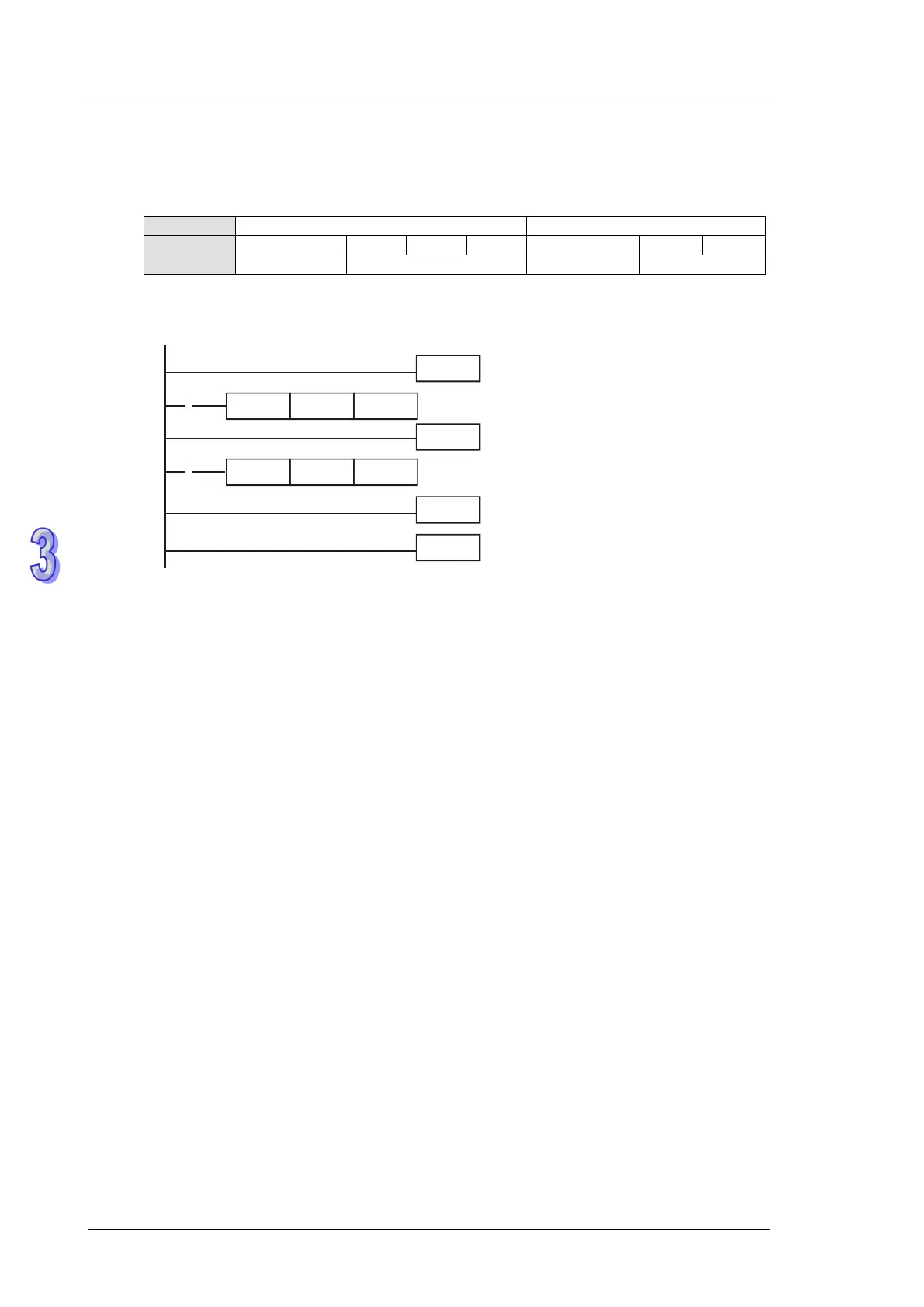
Special D
D1241, D1240
D1243, D1242
Counter
C243
C246
C248
C252
C244
C250
C254
Interrupt
X1(I100/I101)
X4(I400/I401)
X3(I300/I301)
X5(I500/I501)
Program Example 4:
M1000
DCNT
C243 K1
00
EI
FEND
I101
M1000
IRET
END
DMOV
D1240 D0
If interrupt I101 is triggered from input point X1 while C243 is counting, I101 interrupt
subroutine executes immediately and the count value in C243 will be moved to D0. After
this, C243 is reset.

Table of Contents

Other manuals for Delta DVP-SS2

Questions and Answers:

Delta DVP-SS2 Specifications

General IconGeneral
TypePLC (Programmable Logic Controller)
Input Voltage24 VDC
Number of Inputs8
Number of Outputs6
Programming SoftwareWPLSoft
Model/SeriesDVP-SS2
Communication PortsRS-232
Output TypeRelay
High-speed Counters2 points, 10 kHz
Operating Temperature0°C to 55°C
Humidity5% to 95% RH, non-condensing
Dimensions90 mm (H) x 60 mm (W) x 80 mm (D)

Related product manuals