DVP-ES2/EX2/EC5/SS2/SA2/SX2/SE&TP Operation Manual - Programming
-150
4. When D1220/D1221/D1341/D1342= K0, K1,or K2, the positive/negative sign of S
2
denotes
pulse output direction (Positive/negative).
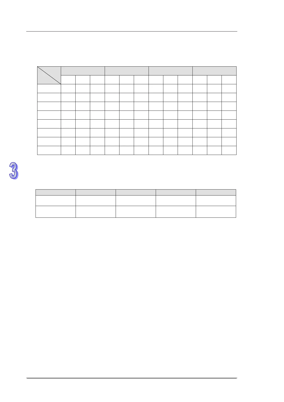
5. Four pulse output modes:
Mode
Output
D1220 D1221 D1341 D1342
K0 K1 K2 K0 K1 K2 K0 K1 K2 K0 K1 K2
Y0 Pulse
Pulse
A
Y1 Dir B
Y2 Pulse
Pulse
A
Y3 Dir B
Y4 Pulse
Pulse
A
Y5 Dir B
Y6 Pulse
Pulse
A
Y7 Dir B
6. Pulse output flags:
Completed Flag
M1029 M1102 M1321 M1322
M1078 M1104 M1310 M1311
a) M1029 = ON after Y0/Y1 (D1220=K1, pulse/Dir) output is completed.
M1102 = ON after Y2/Y3 (D1221=K1, pulse/Dir) output is completed.
M1321 = ON after the Y4/Y5 (D1341 = K1, pulse/Dir) output is completed.
M1322 = ON after the Y6/Y7 (D1342 = K1, pulse/Dir) output is completed.
b) The execution completed flag M1029, M1030, M1321, and M1322 should be manually reset
by users after pulse output is completed.
c) When PLSY / DPLSY instruction is OFF, the pulse output completed flags will all be reset.
7. While the PLSY instruction is being executed, the output will not be affected if S
2
is changed.
To change the pulse output number, stop the PLSY instruction, then change the pulse number.
8. S
1
can be changed during program execution and the change will take effects until the
modified PLSY instruction is being executed.
9. The ratio of OFF time and ON time of the pulse output is 1:1.
10. If operand S
1
, S
2
use index F, only 16-bit instruction is available.
11. There is no limitation on the times of using this instruction, however the program allows only 4
instructions (PLSY, PWM, PLSR) to be executed at the same time. If Y1 is used for several high
speed pulse output instructions, PLC will output according to the execution order of these
instructions.