3. Instruction Set
7. The odd numbered head index values (for example 1, 3, 5,…) are the compared counter
results for the object when entering. The even numbered head index values (for example 2, 4,
6,…) are the compared counter result of the object when leaving.
8. When the compared counter result for entering and leaving in the stack area are 0, the actions
in this area are not executed and the state of the corresponding output work station is OFF.
Add 2 to the value of the tail index and the added value in the tail index should not exceed the
value of the head index.
9. When the YOUT instruction is executed, each work station checks the compared value for
entering and leaving in the tail index. When the counter value is larger or the same as the
compared value for entering, the corresponding output point is ON and adds 1 to the value of
the tail index. When the counter value is larger or the same as the compared value for leaving,
the corresponding output is OFF and adds 1 to the value of the tail index; but the value of the
tail index (after adding 1) does not exceed the value of the head index.
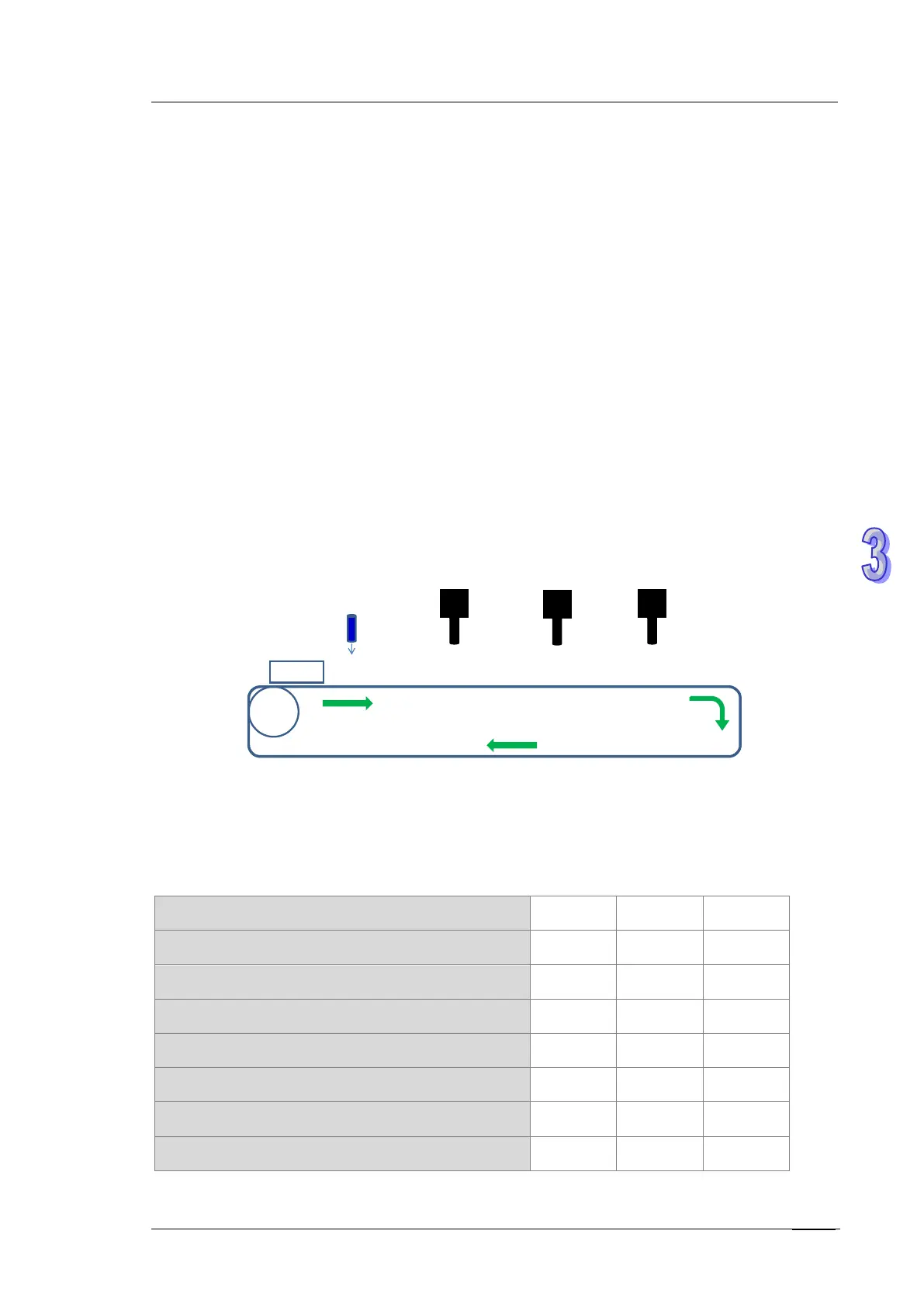
Example: three work stations and up to four objects
Encoder
Object
Work
station
1
Object
detection
Work
station
2
Work
station
3
Step 1: use the input point X4 as the object detection interrupt, C251 as the high-speed counter for
the encoder and output point Y0 as the first output point for the work station.
Step 2: edit the register to set up the reference values, and the observational error when entering
and leaving.
Device D D500 D502 D504
Reference value for comparison (32-bit) K2000 K3000 K4000
Device D D506 D508 D510
Observational error when entering (32-bit) K100 K120 K130
Device D D512 D514 D516
Observational error when leaving (32-bit) K50 K-20 K20
Device D D2000 D2001 D2002
Value of the head index (16-bit) K0 K0 K0
 Loading...


