DVP-ES2/EX2/EC5/SS2/SA2/SX2/SE&TP Operation Manual - Programming
-224
Device D D2003 D2004 D2005
Value of the tail index (16-bit) K0 K0 K0
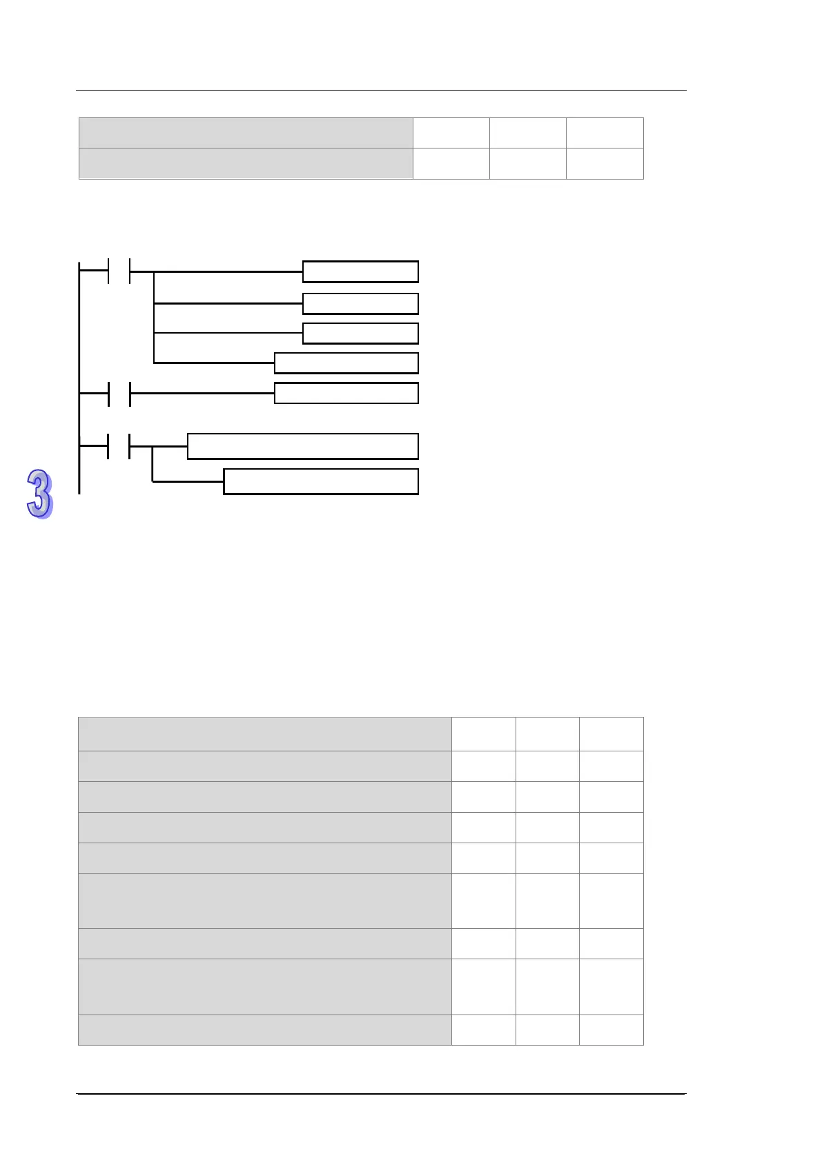
Step 3: set up the initial values and write the programs.
After the contact M0 is activated, the system sets the object detection, the compared values, the
compared counter result of the object entering and leaving, and the output controls for each work
station. For example, the system detects two objects have entered and then four triggers to read the
compared counter results: 3000, 3500, 4500, and 5000 in C251 (C251=K5060). The result of the
last rising-edge / falling-edge of X4 from C251 for the values K4500 and K5000 are stored in (D3,
D4) and (D5, D6) in 32-bit. The following table shows the compared value and the head/tail index in
the stack area.
Device D D2000 D2001 D2002
Value of the head index (16-bit) K4 K4 K4
Device D number D2003 D2004 D2005
Value of the tail index (16-bit) K1 K1 K1
Device D number D2006 D2008 D2010
Compared counter result 1 of the object when entering
(32-bit)
K5100 K
6120 K7130
Device D number D2012 D2014 D2016
Compared counter result 1 of the object when leaving
(32-bit)
K5550 K
6480 K7520
Device D number D2018 D2020 D2022
of pul
Object detection & compared values
Compare & output controls