EasyManua.ls Logo

Delta DVP-SS2

Delta DVP-SS2
1006 pages
To Next Page IconTo Next Page
To Previous Page IconTo Previous Page
Loading...
3. Instruction Set
3-239
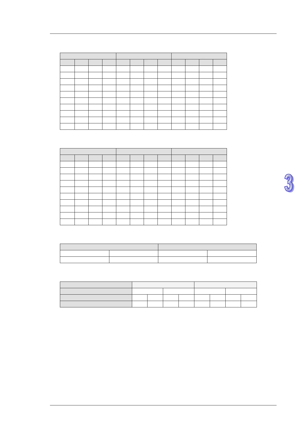
5. Positive logic (negative polarity) output of BCD code
BCD value
Y output (BCD code)
Signal output
b
3
b
2
b
1
b
0
8
4
2
1
A
B
C
D
0
0
0
0
0
0
0
0
1
1
1
1
0
0
0
1
0
0
0
1
1
1
1
0
0
0
1
0
0
0
1
0
1
1
0
1
0
0
1
1
0
0
1
1
1
1
0
0
0
1
0
0
0
1
0
0
1
0
1
1
0
1
0
1
0
1
0
1
1
0
1
0
0
1
1
0
0
1
1
0
1
0
0
1
0
1
1
1
0
1
1
1
1
0
0
0
1
0
0
0
1
0
0
0
0
1
1
1
1
0
0
1
1
0
0
1
0
1
1
0
6. Negative logic (Positive polarity) output of BCD code
BCD value
Y output (BCD code)
Signal output
b
3
b
2
b
1
b
0
8
4
2
1
A
B
C
D
0
0
0
0
1
1
1
1
0
0
0
0
0
0
0
1
1
1
1
0
0
0
0
1
0
0
1
0
1
1
0
1
0
0
1
0
0
0
1
1
1
1
0
0
0
0
1
1
0
1
0
0
1
0
1
1
0
1
0
0
0
1
0
1
1
0
1
0
0
1
0
1
0
1
1
0
1
0
0
1
0
1
1
0
0
1
1
1
1
0
0
0
0
1
1
1
1
0
0
0
0
1
1
1
1
0
0
0
1
0
0
1
0
1
1
0
1
0
0
1
7. Operation logic of output signal
Positive logic (negative polarity)
Negative logic (positive polarity)
Drive signal (latch)
Data control signal
Drive signal (latch)
Data control signal
1
0
0
1
8. Parameter n settings:
Sets of 7-segment display
1 set
2 sets
BCD code data control signal
Drive (latch) signal
n
0
1
2
3
4
5
6
7
’: Positive logic (Negative polarity) output
’: Negative logic (Positive polarity) output
9. The polarity of PLC transistor output and the polarity of the 7-segment display input can be
designated by the setting of n.

Table of Contents

Other manuals for Delta DVP-SS2

Related product manuals