DVP-ES2/EX2/EC5/SS2/SA2/SX2/SE&TP Operation Manual - Programming
API
Mnemonic
Operands Function
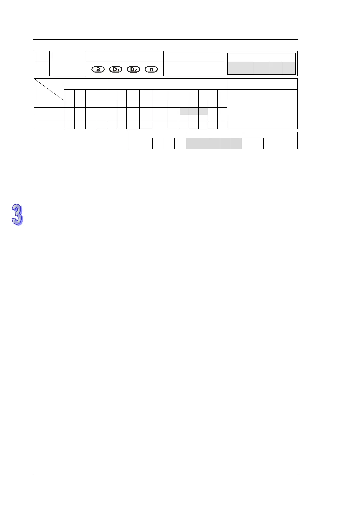
75 ARWS
Arrow switch
Type
OP
Bit Devices Word devices Program Steps
X Y M S K H KnX
KnY
KnM
KnS
T C D E F
ARWS: 9 steps
SS2
SX2
SS2
SX2
SS2
SX2
Operands:
S: Start device for key input (occupies 4 consecutive devices) D
1
: Device storing the value to be
displayed in 7-segment display D
2
: Output device for 7-segment display n: Configuration
setting of output signal (n = 0~3). Please refer to explanations of SEGL instruction for the n usage.
Explanations:
1. ARWS instruction displays the value set in device D
1
on a set of 4-digit 7 segment display.
PLC automatically converts the decimal value in D
1
to BCD format for displaying on the 7
segment display. Each digit of the display can be modified by changing the value in D
1
through
the operation of the arrow switch.
2. Number of D
2
only can be specified as a multiple of 10, e.g. Y0, Y10, Y20…etc.
3. Output points designated by this instruction should be transistor output.
4. When using this instruction, please fix the scan time, or place this instruction in the timer
interruption subroutine (I610/I699, I710/I799).
5. There is no limitation on the times of using this instruction in the program, but only one
instruction is allowed to be executed at a time.
Program Example:
1. When the instruction is executed, X20 is defined as the Minus key, X21 is defined as the Add
key, X22 is defined as the Right key and X23 is defined as the Left key. The keys are used to
modify the set values (range: 0 ~ 9,999) stored in D20..
2. When X0 = ON, digit 103 will be the valid digit for setup. When Left key is pressed, the valid
digit will shift as the following sequence: 103→100→101→102→103→100.
3. When Right key is pressed, the valid digit will shift as the following sequence:
103→102→101→100→103→102. Besides, the digit indicators (LED, Y24 to Y27) will be ON
for indicating the position of the valid digit during shift operation.
4. When Add key is pressed, the content in the valid digit will change as 0 → 1 → 2 … → 8 → 9
→ 0 →1. When Minus key is pressed, the content in the valid digit will change as 0 → 9 → 8 …
→ 1 → 0 → 9. The changed value will also be displayed in the 7-segment display.