3. Instruction Set
3-243
API
Mnemonic Operands Function
77 PR
Print (ASCII Code Output)
Type
OP
Bit Devices Word devices Program Steps
X Y M S K H KnX
KnY
KnM
KnS
T C D E F
PR: 5 steps
SS2
SX2
SS2
SX2
SS2
SX2
Operands:
S: Device for storing ASCII code (occupies 4 consecutive devices) D: External ASCII code output
points (occupies 10 consecutive devices)
Explanations:
1. This instruction will output the ASCII codes in the 4 registers starting from S through output
points started from D.
2. D
0
~ D
7
map to source data (ASCII code) directly in order, D
10
is the scan signal and D
11
is the
execution flag.
3. This instruction can only be used twice in the program.
4. Flags: M1029 (PR execution completed); M1027 (PR output mode selection).
Program Example 1:
1. Use API 76 ASC to convert A ~ H into ASCII codes and store them in D0 ~ D3. After this, use
this instruction to output the codes in sequence.
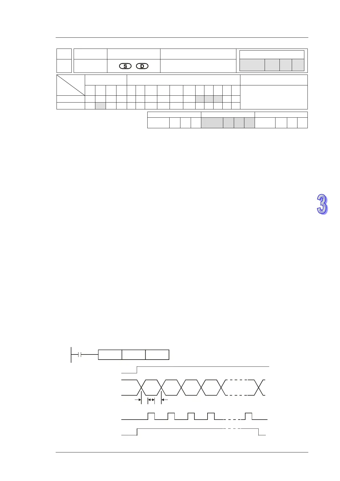
2. When M1027 = OFF and X20 = ON, the instruction will designate Y20 (lowest bit) ~ Y27
(highest bit) as the output points and Y30 as scan signals, Y31 as execution flag. In this mode,
users can execute an output for 8 letters in sequence..
3. If X20 turns from ON → OFF during the execution of the instruction, the data output will be
interrupted, and all the output points will be OFF. When X20 = ON again, the data output will
start from the first letter again.
T T T
A B C D H
X20 start signal
Y20~Y27 data
Y30 scan signal
Y31 being executed
T : scan time(ms)