DVP-ES2/EX2/EC5/SS2/SA2/SX2/SE&TP Operation Manual - Programming
Program Example 2:
1. PR instruction supports ASCII data output of 8-bit data string when M1027 = OFF. When
M1027 = ON, the PR instruction is able to execute an output of 1~16 bit data string.
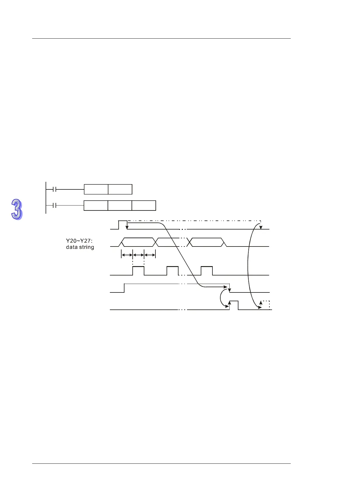
2. When M1027 = ON and X20 = ON, this instruction will designate Y20 (lowest bit) ~ Y27
(highest bit) as the output points and Y30 as scan signals, Y31 as execution flag. In this mode,
users can execute an output for 16 letters in sequence. In addition, if the drive contact X20 is
OFF during execution, the data output will stop until a full data string is completed.
3. The data 00H (NULL) in a data string indicates the end of the string and the letters coming after
will not be processed.
4. If the drive contact X20 is OFF during execution, the data output will stop until a full data string is
completed. However, if X20 remains ON, execution completed flag M1029 will not be active as
the timing diagram below.
X20
PR D0 Y20
M1002
SET
M1027
T T T
last letter
first letter
T : scan time or
i
nterrupt time
X20: drive signal
Y30: scan signal
Y31: execution status
M1029: execution
completed flag
Points to note:
1. Please use transistor output for the output points designated by this instruction.
2. When using this instruction, please fix the scan time or place this instruction in a timer interrupt
subroutine.