EasyManuals Logo
Home>Delta>Controller>DVP-SS2

Delta DVP-SS2 User Manual

Delta DVP-SS2
1006 pages
To Next Page IconTo Next Page
To Previous Page IconTo Previous Page
Page #470 background imageLoading...
Page #470 background image
3. Instruction Set
3-349
The error checksum LRC CHK (0, 1) can be calculated by LRC instruction (8-bit mode, M1161 =
ON).
M1000
LRC D101 K12 D113
LRC checksum: 01 H + 03 H + 07 H + 08 H + 00 H + 06 H = 19 H. Operate 2’s complement on 19H
and the result is E7H. Store ‘E’(45 H) in the low byte of D113 and ‘7’ (37 H) in the low byte of D114.
Remarks:
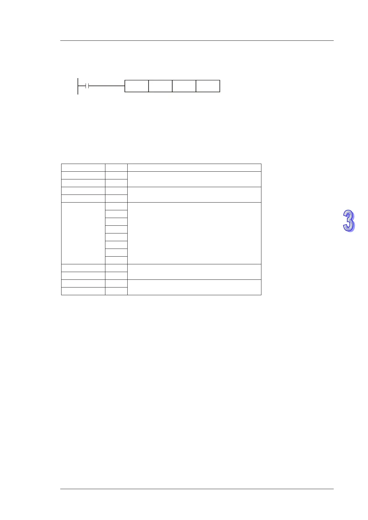
ASCII mode communication data:
STX
‘: ’
Start word = ‘: ’ (3AH)
Address Hi
‘ 0 ’
Communication:
8-bit address consists of 2 ASCll codes
Address Lo
‘ 1 ’
Function Hi
‘ 0 ’
Function code:
8-bit function consists of 2 ASCll codes
Function Lo
‘ 3 ’
DATA (n-1)
…….
DATA 0
‘ 2 ’
Data content:
n × 8-bit data consists of 2n ASCll
codes
‘ 1 ’
‘ 0 ’
‘ 2 ’
‘ 0 ’
‘ 0 ’
‘ 0 ’
‘ 2 ’
LRC CHK Hi
‘ D ’
LRC checksum:
8-bit checksum consists of 2 ASCll codes
LRC CHK Lo
‘ 7 ’
END Hi
CR
End word:
END Hi = CR (0DH), END Lo = LF(0AH)
END Lo
LF
LRC checksum: Operate 2’s complement on the summed up value from communication address
to the end of data, i.e. 01 H + 03 H + 21 H + 02 H + 00 H + 02 H = 29 H, the operation result of 29H
is D7H.

Table of Contents

Other manuals for Delta DVP-SS2

Questions and Answers:

Question and Answer IconNeed help?

Do you have a question about the Delta DVP-SS2 and is the answer not in the manual?

Delta DVP-SS2 Specifications

General IconGeneral
BrandDelta
ModelDVP-SS2
CategoryController
LanguageEnglish

Related product manuals