EasyManuals Logo
Home>Delta>Controller>DVP-SS2

Delta DVP-SS2 User Manual

Delta DVP-SS2
1006 pages
To Next Page IconTo Next Page
To Previous Page IconTo Previous Page
Page #469 background imageLoading...
Page #469 background image
DVP-ES2/EX2/EC5/SS2/SA2/SX2/SE&TP Operation Manual - Programming
3-348
Program Example:
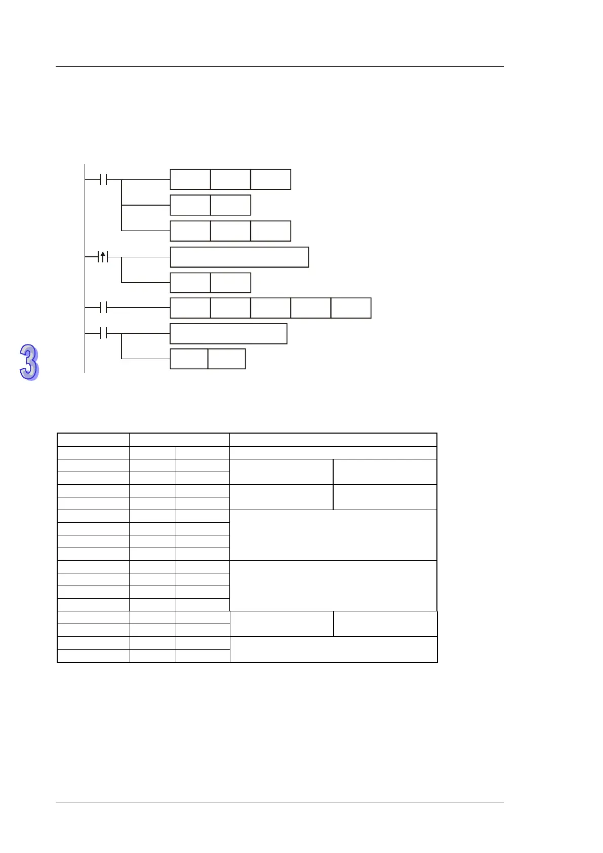
Connect PLC to VFD series AC motor drive (ASCII mode, M1143 = OFF), (8-bit mode, M1161 = ON),
Write the data to be sent into registers starting from D100 in advance for reading 6 data from
address H0708 on VFD.
MOV D1120H86
M1002
SET M1120
SET M1122
MOV D1129K100
X10
M1123
RST
M1123
RS D100
K17
D120 K35
pulse
Receiving completed
Processing received data
S e t u p
communication protocol to 9600, 7, E, 1
Retain communication protocol
S e t u p c o m m u n ic a tio n tim e -o u t: 1 0 0 m s
Sending request
Reset M1123
Write data to be sent in advance
Sending request pulse
PLC VFD, PLC sends: “: 01 03 07 08 0006 E7 CR LF ”
Registers for sent data (sending messages)
Register
Data
Explanation
D100 low byte
‘: ’
3A H
STX
D101 low byte
‘0’
30 H
ADR 1
Address of AC motor
drive: ADR (1,0)
D102 low byte
‘1’
31 H
ADR 0
D103 low byte
‘0’
30 H
CMD 1
Command code:
CMD (1,0)
D104 low byte
‘3’
33 H
CMD 0
D105 low byte
‘0’
30 H
Starting data address
D106 low byte
‘7’
37 H
D107 low byte
‘0’
30 H
D108 low byte
‘8’
38 H
D109 low byte
‘0’
30 H
Number of data (words)
D110 low byte
‘0’
30 H
D111 low byte
‘0’
30 H
D112 low byte
‘6’
36 H
D113 low byte
‘E’
45 H
LRC CHK 0
Error checksum: LRC
CHK (0,1)
D114 low byte
‘7’
37 H
LRC CHK 1
D115 low byte
CR
D H
END
D116 low byte
LF
A H

Table of Contents

Other manuals for Delta DVP-SS2

Questions and Answers:

Question and Answer IconNeed help?

Do you have a question about the Delta DVP-SS2 and is the answer not in the manual?

Delta DVP-SS2 Specifications

General IconGeneral
BrandDelta
ModelDVP-SS2
CategoryController
LanguageEnglish

Related product manuals