DVP-ES2/EX2/EC5/SS2/SA2/SX2/SE&TP Operation Manual - Programming
Program example 14: COM1 (RS-232)/ COM3 (RS-485), Function Code H17
1. Function code K23 (H17): Data is read from multiple word devices and data is written into
multiple word devices. Data can be read from 16 word devices at most, and data can be written
into 16 word devices at most.
2. In the ASCII or RTU mode, the data received through COM1/COM3 on the PLC is stored in the
registers starting from the register indicated by the index value in S+1. Users can use the
instruction DTM to transform and move the data.
3. The connection between PLC-A (PLC COM3) and PLC-B:
Data is written into multiple word devices in PLC-B from PLC-A. (M1320=OFF, ASCII Mode)
(M1320=ON, RTU Mode)
If COM1 on PLC-A is connected, the program can be modified as shown below.
a) D1109→D1036: Communication protocol
b) M1136→M1138: The communication setting is retained.
c) D1252→D1249: Communication timeout
d) M1320→M1139: Choice between the ASCII mode and the RTU mode
e) M1316→M1312: The sending of the data though the communication instruction is
requested.
f) M1318→M1314: The receiving of the data through the communication instruction is
complete.
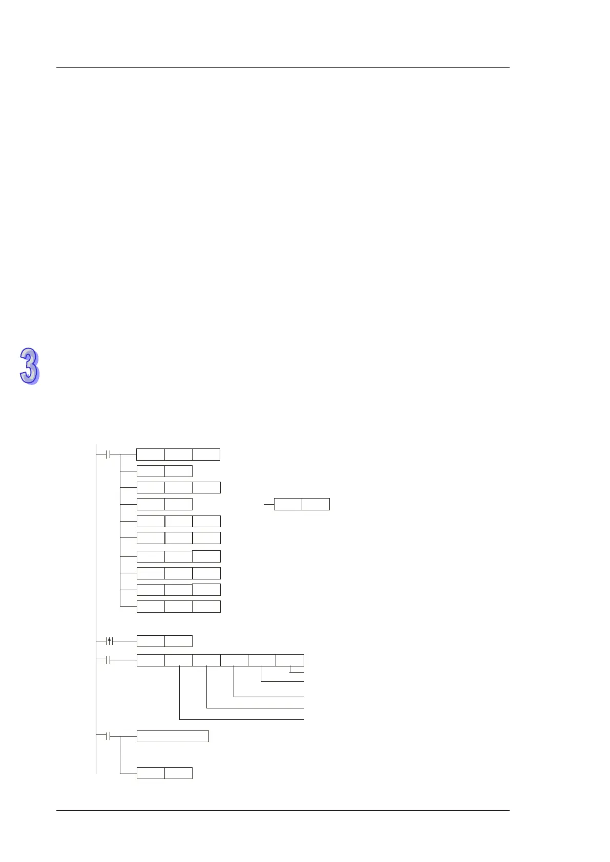
Set communication protocol as 9600, 8, E, 1
Retain communication protocol
Set communication timeout as 100ms
Connection device
address: K1
Function code: K23
The data is read from/written into multiple word devices.
Processing received data
ASCII mode : The received ASCII data is stored in the registers starting from D3000 i .
n Hex value
RTU mode : The received data is stored in the registers starting from D3000 in Hex value.
Reset M1318
Sending request
M1320 = OFF
ASCII mode
M1320 = ON
RTU mode
The data is read from the address H1100.
The data is written into the address H1000.
The data is read into D3000.
The data is written from D4000.
The length of the data which is read is K2.
The length of the data which is written is K2.
D20: Length of the data read
D21: Length of the data written
D0: Address from which the data is read
D1: Address into which the data is written
D10:The index value indicates the register into which the data is read.
D11: The index value indicates the register from which the data is written.
H87
MOV
M1002
D1109
SET
M1136
K100
MOV
D1252
RST
M1318
MODRW
K23
K1
X0
D0 D10
D20
M1318
SET
X0
M1316
RST
M1320
SET
M1320
H1100
MOV
D0
H1000
MOV
D1
K3000
MOV
D10
K4000
MOV
D11
K2
MOV
D20
K2
MOV
D21