3. Instruction Set
functions as a source device at first, and then functions as a destination device when a reading
command is executed.
Note
#2
: If a communication combination command is used, S
2
+1 and S
2
+2 will be set by the PLC
according to the communication combination command.
D
1
is a source device or a destination device. Please refer to the description of the function codes
above.
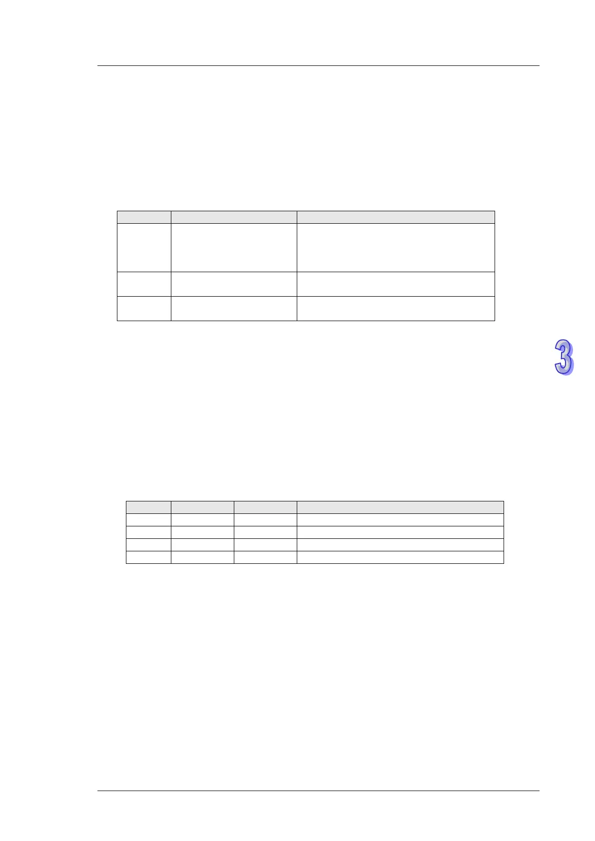
D
2
is a communication state flag. It occupies three consecutive devices. It is described below.
D
2
+0 The DMV is busy.
If the DMV is busy, a communication
command will be resent automatically until
the DMV replies that the communication is
D
2
+1
The communication with
the DMV is complete.
D
2
+2
Communication error or
timeout
The DMV does not reply after a timeout
period.
Whenever the instruction is enabled, the PLC automatically reset D
2
to Off.
Example 1: Users define a DMV communication command. COM2 on a PLC communicates with a
DMV. H0888 is written into the communication address H10D0 in the DMV. The control procedure is
described below.
1-1: Write K2 into D0. (COM2 on the PLC is used.) Write K1 into D1. (The station address of the
DMV is K1.)
1-2: Write K0 into D4. The users define a DMV communication command by themselves, and write
the command message into D5~D7.
Communication combination function code
Communication data length
1-3: When M0 is On, the PLC communicates with the DMV according to the communication data
and the communication port set by the users, and H0888 in D8 is written into H10D0 in the
DMV.
1-4: When the PLC sends the data, the operand D
2
(Y0) is On (the DMV is busy).
1-5: When the DMV replies successfully, D
2
+1 (Y1) in the PLC is On (the communication with the
DMV is complete).
1-6: If the DMV does not reply after the timeout period 100ms, the PLC will set D
2
+2 (Y2) to On (a
communication timeout occurs).
1-7: If the DMV replies with an execption code, the PLC will resend the command to the DMV
automatically, and go back to step 1-3 ~ step 1-5.