DVP-ES2/EX2/EC5/SS2/SA2/SX2/SE&TP Operation Manual - Programming
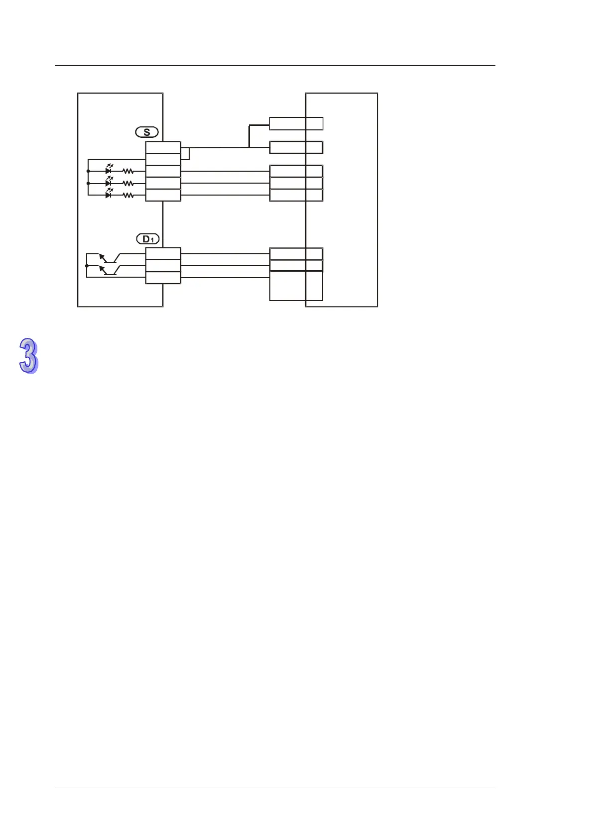
PLC Controller
DVP32ES200T
ABSR
ABSD
ABSE
ABSQ
SERVO DRIVE
ASDA-A2
CN1
DO2+ 5
3DO3+
DOx+
8
45,
47,
49
DIx-
DI4-
COM-
X0
X1
X2
S/S
UP0
Y4
Y5
ZP0
VDD 17
ABSW
COM+ 11
6. D
2
will occupy 4 consecutive devices D
2
, D
2
+1. D
2
+2, and D
2
+3. The absolute acoordinate
system status (P0-50) is stored in D
2
, the encoder absolute position (multiturn) (P0-51) is
stored in D
2
+1. The lower 16 bits of the encoder absolute position (pulse number within
singleturn or PUU) (P0-52) is stored in D
2
+2. The higher 16 bits of the encoder absolute
position (pulse number within singleturn or PUU) (P0-52) is stored in D
2
+3.
7. After the the reading of the absolute positio of a servo through the instruciton DABSR is
complete, M1580 will be On. If an error occurs during the execution of the instruciton, M1581
will be On.
8. When driving the DABSR command, please specify normally open contact. If the drive contact
of DABSR command turns Off when DABSR command read starts, the execution of absolute
current value read will be interrupted and result in incorrect data. Please be careful and notice
that.
9. If the input signals are from the high-speed input points X0~X7, it takes 2 seconds for the
instruction to be executed. if the input signals are form the input points following X10, it takes
2.5 seconds for the instruciton to be executed. The time it takes for the instruction to be
executed is affected by the scan time.
Program Example: (for DVP-ES2/EX2 series PLCs whose version is 3.00; DVP-SA2 series
PLCs whose version is 2.40; DVP-SE series PLCs whose version is 1.20;
DVP-SX2 series PLCs whose veresion is 2.20; DVP-SS2 series PLCs (and
below))
1. When X7 = ON, the 32-bit absolute position data read from Mitsubishi MR-J2 servo will be
stored in the registers D0~D1. At the same time, timer T0 is enabled and starts to count for 5
seconds. If the 32-bit instruction is not completed within 5 seconds, M10 will be ON, indicating
operation errors.