3. Instruction Set
Explanations (Applicable to EC5 Series):
1. The instruction only supports the pulse output type: Pulse + Direction.
2. S
1
is the number of pulses (relative positioning). Available range: -2,147,483,648 ~
+2,147,483,647. “+/-” signs indicate forward and reverse direction.
3. D1340 (D1352, D1379, D1380) is start/end frequency setting of CH0 (CH1, CH2, CH3). Even
if the value in S
2
is less than the starting /ending frequency, it still outputs the freuency as the
value in S
2
indicated.
4. The special D and special M:
CH0 CH1 CH2 CH3
Pulse output device (D
1
) Y0 Y2 Y4 Y6
Directon signal ouptut (D
2
) Y1 Y3 Y5 Y7
Reverse pulse output direction M1305 M1306 M1532 M1533
Current position
Ramp up / down time of the 1st
group pulse output
D1343 D1353 D1381 D1382
Start / end frequency of the 1st
group pulse output
D1340 D1352 D1379 D1380
Enable ramp-down time setting M1534 M1535 M1536 M1537
Ramp-down time D1348 D1349 D1350 D1351
Pulse output pause (immediate) M1078 M1104 M1310 M1311
Pause state M1538 M1540 M1542 M1543
Ramp-down when the
conditional contacts are closed.
M1334 M1335 M1520 M1521
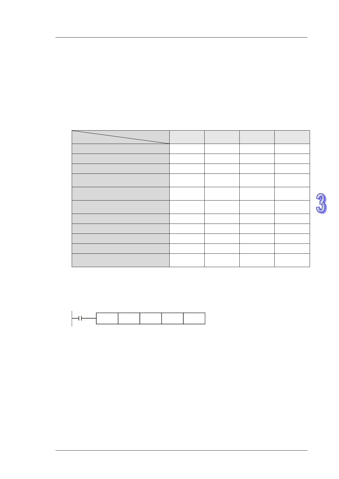
Program Example:
When M10= ON, 20,000 pulses (relative position) at 2kHz frequency will be generated from Y0. Y1=
OFF indicates positive direction.
M10
DDRVI K20000 K2000 Y0 Y1
Points to note:
1. Operation of relative positioning:
Pulse output executes according to the relative distance and direction from the current position