DVP-ES2/EX2/EC5/SS2/SA2/SX2/SE&TP Operation Manual - Programming
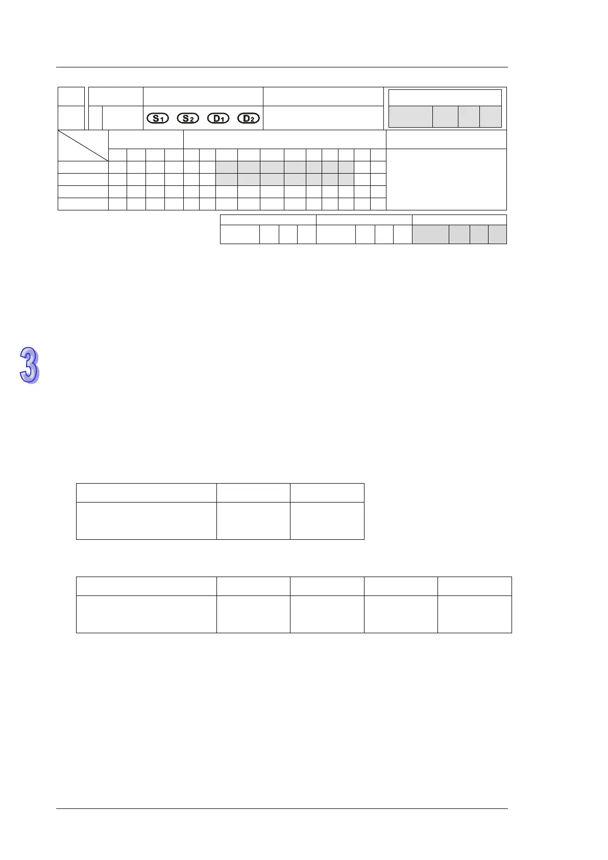
API
Mnemonic
Operands Function
159 D DRVA
Absolute Position
Control
OP
Bit Devices Word devices Program Steps
DRVA: 9 steps
DDRVA: 17 steps
SS2
SX2
SS2
SX2
SS2
SX2
Operands:
S
1
: Numbers of pulses (Absolute positioning) S
2
: Pulse output frequency D
1
: Pulse output
device D
2
: Direction signal output
Explanations (Applicable to ES2, EX2, SS2, SA2, SE, SX2 Series):
1. The instruction only supports the pulse output type: Pulse + Direction.
2. S
1
is the number of pulses (Absolute positioning). Available range: -2,147,483,648 ~
+2,147,483,647. “+/-” signs indicate forward and reverse direction.
5. S
2
is the pulse output frequency. Available range: 6 ~ 100,000Hz.
6. D
1
is the pulse output device. It can designate CH0 (Y0) and CH1 (Y2).
7. D
2
is the direction signal output device. If Y output is designated, only CH0 (Y1) and CH1 (Y3)
are available.
Pulse output device (D
1
) Y0 Y2
Corresponding direction
signal output device (D
2
)
Y1 Y3
8. ES2/EX2: V3.46, ES2-C: V3.48, ES2-E: V1.00, 12SE: V2.02, 26SE: V1.0 and later versions
support the settings in D
1
and D
2
as shown below.
Pulse output device (D
1
) Y0 Y1 Y2 Y3
Corresponding direction
signal output device (D
2
)
Y4 Y5 Y6 Y7
9. S
1
is the target position for absolute positioning. The actual number of output pulses (S
1
–
current position) will be calculated by PLC. When the result is positive, pulse output
executes forward operation, i.e. D
2
= OFF; when the results is negative, pulse output
executes reverse operation, i.e. D
2
= ON.
10. The set value in S
1
is the absolute position from zero point. The calculated actual number of
output pulses will be the relative position of
- current position (32-bit data) of CH0 (Y0, Y1) which is stored in D1031(high), D1030 (low)
- current position (32-bit data) of CH1 (Y2, Y3) which is stored in D1337(high), D1336 (low).