DVP-ES2/EX2/EC5/SS2/SA2/SX2/SE&TP Operation Manual - Programming
8. For pulse output with ramp-up/down section, if only 1 axis is specified with pulse output number,
i.e. another axis is 0, the pulse output will only be performed on the axis with output pulse
number. However, if the output pulse number is less than 20 in any of the 2 axes, the
ramp-up/down section will be disabled and pulse output will be executed with the frequency not
higher than 3kHz.
9. There is no limitation on the number of times for using the instruction. However, assume CH0 or
CH1 pulse output is in use, the X/Y axis synchronized output will not be performed.
10. M1029 will be ON when 2-axis synchronized pulse output is completed.
Program Example:
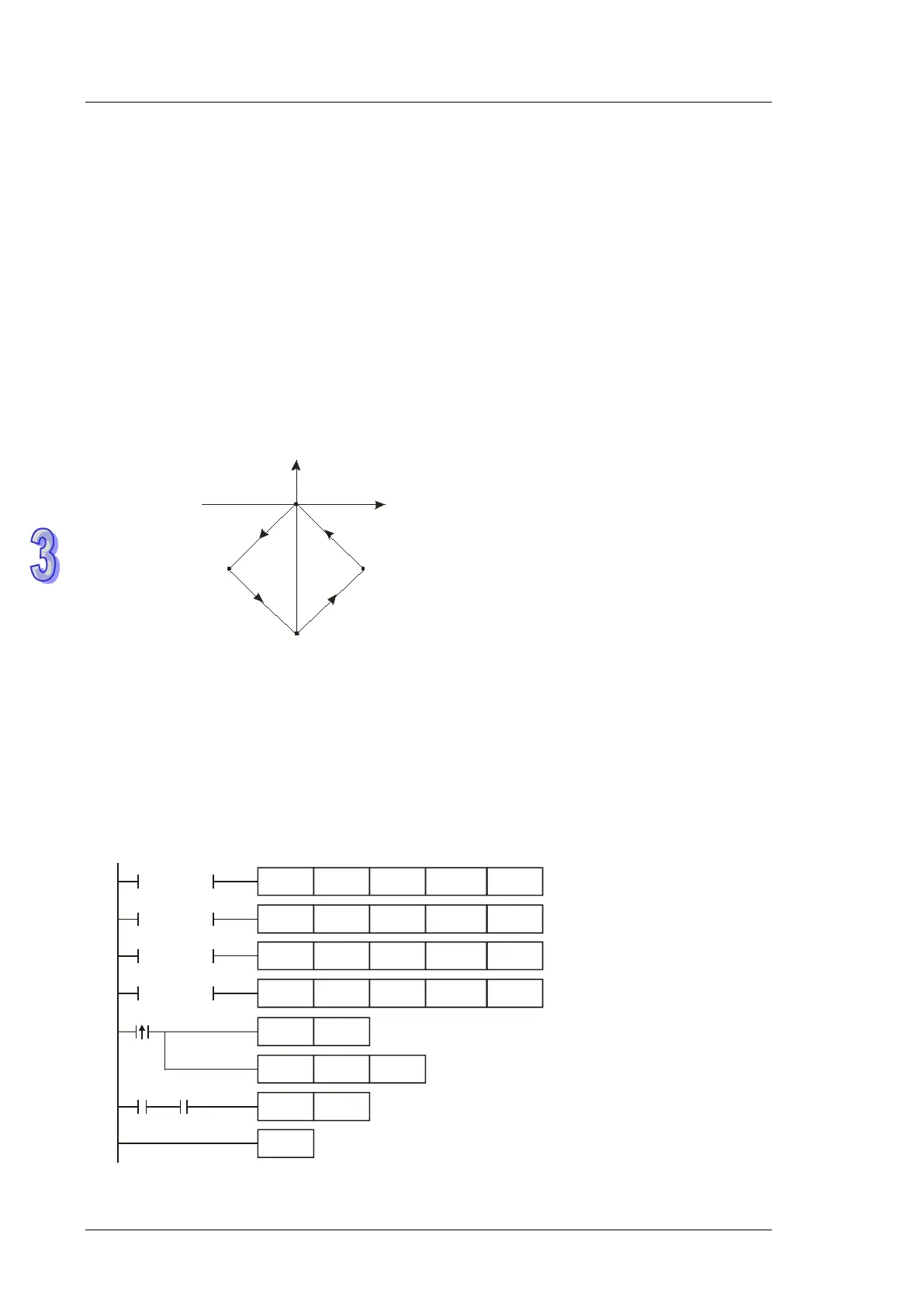
1. Draw a rhombus as the figure below.
(0,0)
(-27000,-27000)
(0,-55000)
(
27000,-27000)
X
Y
Steps:
a) Set the four coordinates (0,0), (-27000, -27000), (0, -55000), (27000, -27000) (as the figure
above). Calculate the relative coordinates of the four points and obtain (-27000, -27000),
(27000, -28000), (27000, 27000), and (-27000, 27000). Place them in the 32-bit registers
(D200, D202), (D204, D206), (D208, D210), (D212, D214).
b) Design instructions as follows.
c) RUN the PLC. Set ON M0 to start the 2-axis line drawing.
M0
RST
= D0 K1
DPPMR D200
D202 K100000
Y0
= D0 K2
DPPMR D204
D206 K100000
Y0
= D0 K3
DPPMR D208
D210 K100000
Y0
= D0 K4
DPPMR D212
D214 K100000
Y0
MOV D0
M0
INCP
END
M1029
D0
M1029
K1