DVP-ES2/EX2/EC5/SS2/SA2/SX2/SE&TP Operation Manual - Programming
API
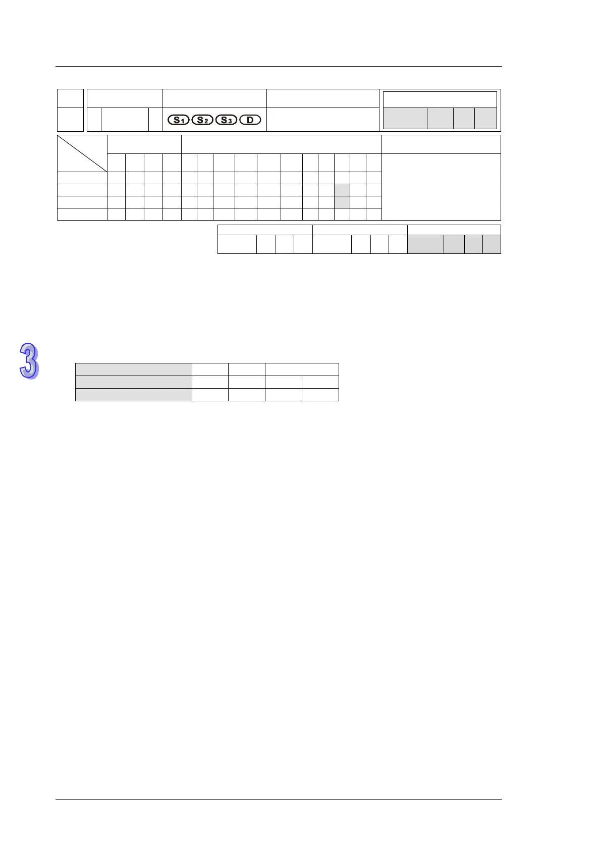
Mnemonic Operands Function
197 D
CLLM
Close loop position
control
Type
OP
Bit Devices Word devices Program Steps
X Y M S K H KnX
KnY
KnM
KnS
T C D E F
DCLLM: 17 steps
ES2/EX2 SS2
SX2
ES2/EX2
SS2
SX2
ES2/EX2
SS2
SX2
Operands:
S
1
: Feedback source device S
2
: Target number of feedbacks S
3
: Target frequency of output
D: Pulse output device
Explanations:
1. The corresponding interrupt pointers of S
1
:
= 1: rising-edige triggered; = 0: falling-edge triggered
a) When S
1
designates input points X and the pulse output reaches the target number of
feedbacks in S
2
, the output will continue to operate by the frequency of the last shift (end
frequency) until interrupts occur on input points X.
b) When S
1
designates high speed counters and the pulse output reaches the target number
of feedbacks in S
2
, the output will continue to operate by the frequency of the last shift
(end frequency) until the feedback pulses reaches the target number.
c) S
1
can be a high speed counter C or an input point X with external interrupt. If S
1
is C,
DCNT instruction should be executed in advance to enable the high-speed counting
function, and EI instruction with I0x0 should be enabled for external interrupts. If S
1
is X, EI
instruction with I0x0 should be enabled for external interrupts.
d) If S
1
is specifed with counters, DHSCS instruction has to be programmed in user program.
Please refer to Program example 2 for details.
2. Range of S
2
: -2,147,483,648 ~ +2,147,483,647 (+ / - indicates the positive / negative rotation
direction). the present value of pulse output in CH0 (Y0, Y1) and CH1 (Y2, Y3) increases in
positive direction and decreases in negative direction. Registers storing present value of pulse
output: CH0(D1031 High, 1030 Low), CH1(D1337 High, D1336 Low)
3. If S
3
is lower than 6Hz, the output will operate at 6Hz; if S
3
is higher than 100kHz, the output
will operate at 100kHz.
4. D can only designate Y0 (Direction signal output: Y1) or Y2 (Direction signal output: Y3). The
 Loading...