3. Instruction Set
direction signal output will be OFF only when the drive contact of the instruction is OFF, i.e.
completion of pulse output will not reset Y1 or Y3.
5. D1340 and D1352 stores the start/end frequencies of CH0 and CH1. Min. 6Hz, default:
100Hz.
6. D1343 and D1353 stores the ramp up/down time of CH0 and CH1. If the ramp up/down time is
shorter than 20ms, PLC will operate in 20ms. Dafault: 100ms.
7. Ramp-down time of CH0 and CH1 can be particularlily specified by the setting of (M1534,
D1348) and (M1535, D1349). When M1534 / M1535 is ON, ramp-down time of CH0 and CH1 is
set by D1348 and D1349.
8. D1131 and D1132 are the output/input ratio(%) of the close loop control in CH0 and CH1. K1
refers to 1 output pulse out of 100 feedback pulses; K200 refers to 200 output pulses out of the
100 feedback pulses. In general percentage equation, the value set in D1131 and D1132
represents numerators (output pulses, available range: K1 ~ K10,000) and the denominator
(the input feedbacks) is fixed as K100 (System defined).
9. M1305 and M1306 can reverse the direction of CH0, CH1 pulse output. For example, when
direction signal output (Y1/Y3) is OFF, pulse output will operate in positive direction. If
M1305/M1306 is set ON before the execution of this instruction, the pulse output will be
reversed as negative output direction.
10. When S
1
designates input points X with interrupt pointers, D1244 / D1255 can be applied for
setting the idle time as limited pulse number, in case the interrupt is not properly triggered.
11. DCLLM instruction supports Alignment Mark and Mask function. Please refer to PLSR
instruction for details.
Close Loop Explanations:
1. Function: Immediately stop the high-speed pulse output according to the number of feedback
pulses or external interruption signals.
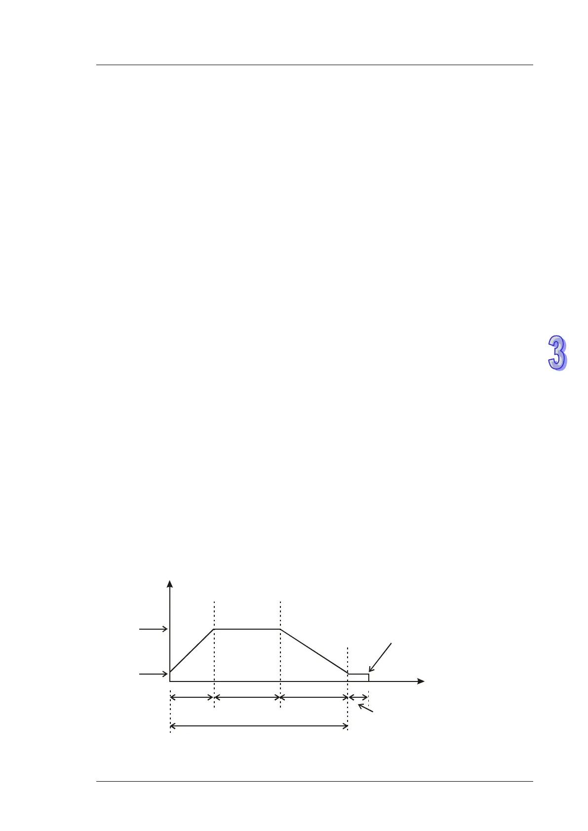
2. Timing diagram:
Frequency
Time
Pulse Number
High speed counter receives
target number of feedbacks
or
External interrupt occurs
Target
frequency
Start/end
frequency
Ramp-up
time
High speed time Ramp-down
time Idle time
Number of output pulses =
target number of feedbacks x D1131(D1132) / 100