3. Instruction Set
exceeds the maximum frequency, the instruction would be executed at the maximum
frequency. But changing the speed would not change the direction. To change the direction,
set the value of TarSpeed to 0 first and then modify the target speed.
6. The instruction can be used with the software and hardware limit points. When the limits are
triggered, the output stops immediately and the Error flag changes to ON.
7. If any error occurs as the instruction is in process of the output, the Error flag changes to ON.
Refer to the error codes that ErrCode shows for the trouble shooting.
8. The error codes that ErrCode shows are listed in the following table.
Error code Description
16#1400 The module does not support the function.
16#1402 There is no response from the module; communication timeout occurs.
16#1403 There is no such output axis number in the PU module.
16#1405
The output axis specified by the PU module is outputting data. It is not
allowed to specify the output repeatedly.
16#1406 PU module stops Output pulse when the positive limit is reached.
16#1407 PU module stops Output pulse when the negative limit is reached.
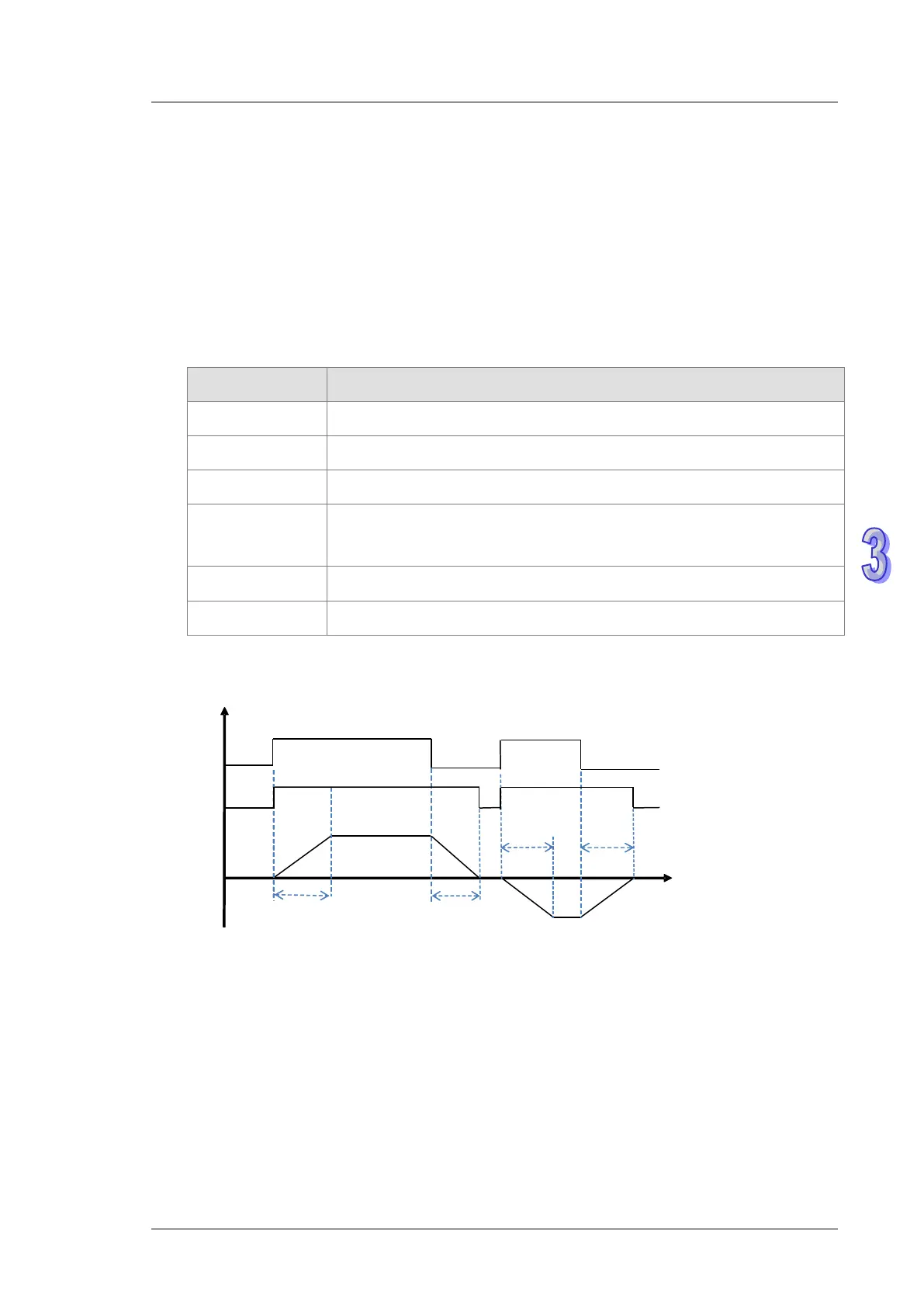
9. See the output timing diagram as below. (Jog_in is the switch to start the instruction and the
Busy flag is the Busy flag.)
Jog_in
Increase
JogSpeed > 0
Time
Decrease
0
Busy flag
Increase Decrease
JogSpeed < 0
10. After the PUJOG instruction is disabled and the Busy flag is off, other output control can be
carried out.