3. Instruction Set
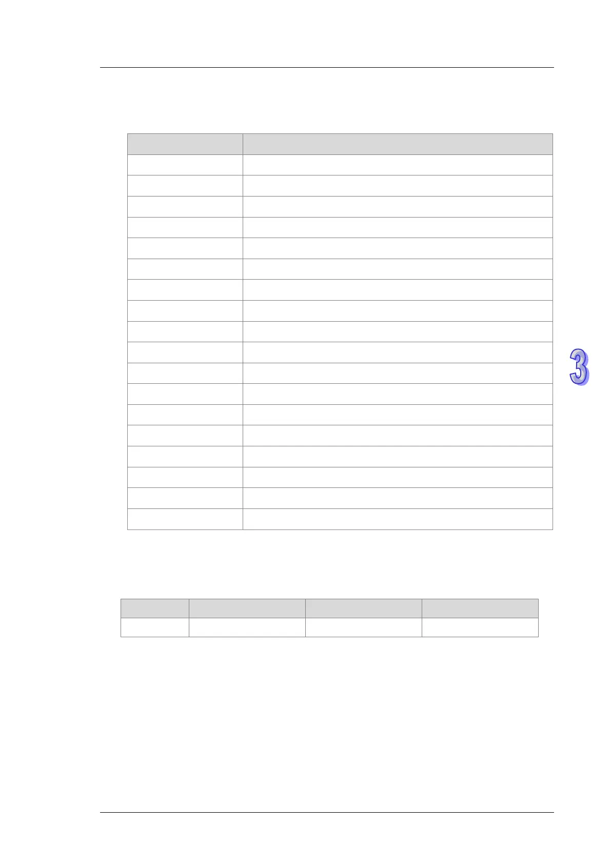
4. XMode selects an input mode for input points. Setting values are explained in the following
table:
Setting in XMode DVP02PU-E2
0 General input (Default)
1 Axis 1, Z phase, Rising-edge triggered
2 Axis 2, Z phase, Rising-edge triggered
3 Axis 1, Z phase, Falling-edge triggered
4 Axis 2, Z phase, Falling-edge triggered
5 Axis 1, DOG, Rising-edge triggered
6 Axis 2, DOG, Rising-edge triggered
7 Axis 1, DOG, Falling-edge triggered
8 Axis 2, DOG, Falling-edge triggered
9 Axis 1, LSN, Rising-edge triggered
10 Axis 2, LSN, Rising -edge triggered
11 Axis 1, LSN, Falling-edge triggered
12 Axis 2, LSN, Falling-edge triggered
13 Axis 1, LSP, Rising-edge triggered
14 Axis 2, LSP, Rising-edge triggered
15 Axis 1, LSP, Falling-edge triggered
16 Axis 2, LSP, Falling-edge triggered
Other Automatically switch to mode 0 (default)
5. Xfilter is explained in the following table. The value in Xfilter is the default value if the setting
is out of the allowed range.
Parameter Function Range Default
Xfilter Input point filter time 0 ~ 25 (unit:ms) 10
6. Done, an output of the specified PU module has been set as the completion flag. When Done
is On, it indicates that the parameter setting is successful. You can continue to perform
positioning output based on the state of the completion flag (ON). The clearing of the Done
flag need be conducted by manual. The Done flag changes to ON only when the setting is
completed.
7. Error, an output of the specified PU module is a parameter error flag. Most parameter ranges
are filtered automatically by the PLC. Thus if the error flag is ON, it means that there is no