DVP-ES2/EX2/EC5/SS2/SA2/SX2/SE&TP Operation Manual - Programming
Example:
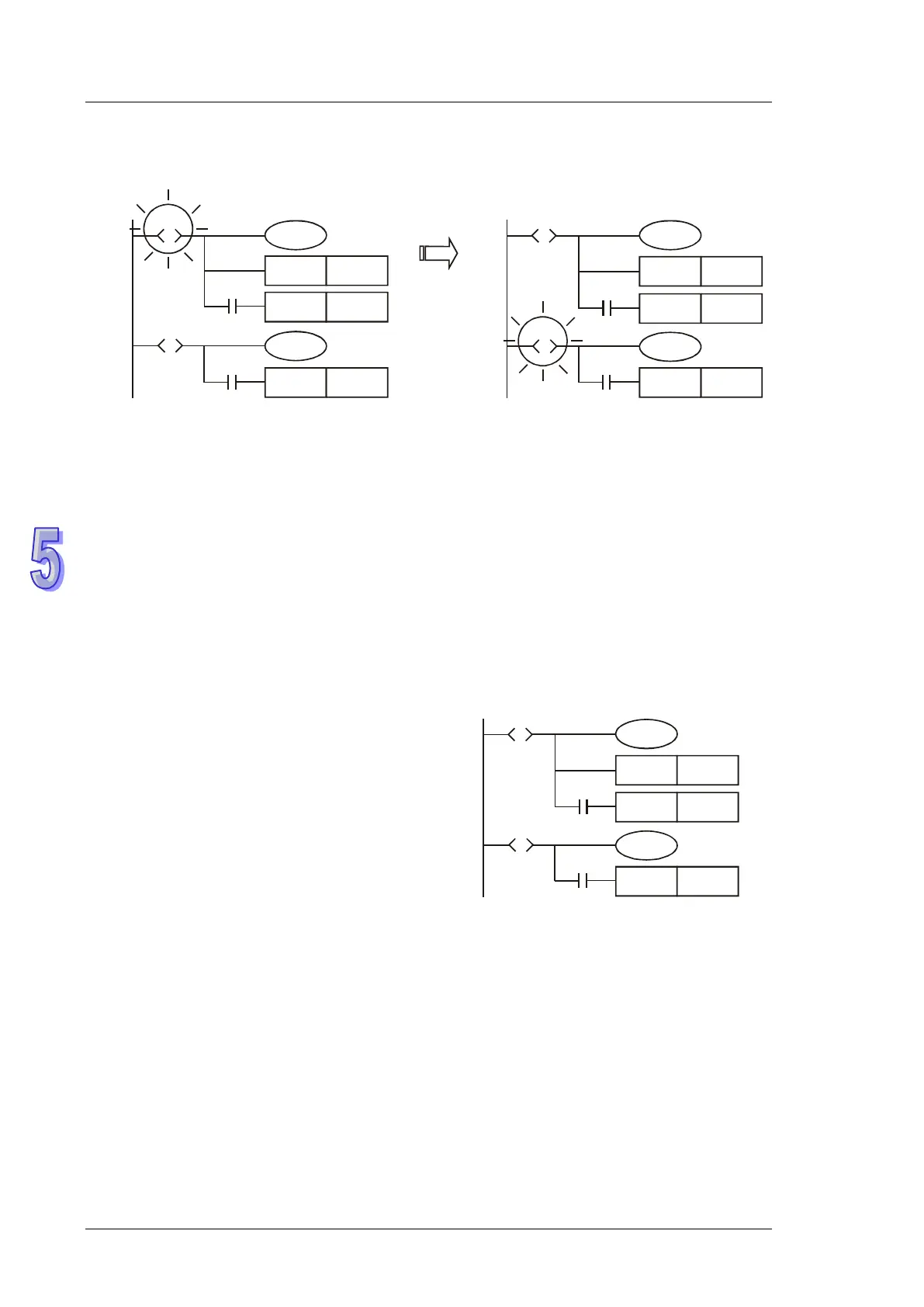
SET Y1
Y0
SET S20
Y20
SET S30
S10
S
X0
S20
S
X1
SET Y1
Y0
SET S20
Y20
SET S30
S10
S
X0
S20
S
X1
When X0 = ON,
S20 = ON,
S10 = OFF
.
Explanation:
When S10 = ON, Y0 and Y1 will be ON. When X0 = ON, S20 will be ON and Y20 will be ON. When
S10 = OFF, Y0 will be OFF but Y1 will still be ON (SET instruction is applied on Y1, so Y1 will be ON
and latched.)
STL Transition:
When step point Sn
is ON, its following output circuit will be activated. When Sn = OFF, its following
output circuit will be OFF. The interval between the activation of the step point and its following
output circuit is one scan cycle.
Repeated Usage of Output Coil:
1.
Output coils of the same number could be used
in different step points.
2. See the diagram opposite. There can be the
same output device (Y0) among different steps
(sequences). Y0 remains ON when S10
transfers to S20.
3. Y0 will be OFF due to the transition from S10 to
S20. However when S20 is ON, Y0 will be ON
again. Therefore in this case, Y0 remains ON
when S10 transfers to S20.
SET Y1
Y0
SET S20
SET S30
S10
S
X0
S20
S
X1
Y0
4. For general ladder diagrams, repeated usages of output coils should be avoided. The No. of
output coil used by a step should also avoid being used when the step ladder diagram returns
to a general ladder diagram.
5. Note:
If the operands are qualified by E or F, the repeated usages of output coils in the steps
is no longer allowed, e.g. OUT Y0E1.