Load Cell Module DVP02LC-SL
DVP-PLC Operation Manual
34
y Program explanations
1. The PLC switches from STOP to RUN. Due to the range for analog output voltage for the
brake system is 0 to 10 VDC, we first set the voltage output mode for DVP04DA-SL to “0”
(-10 to +10 V).
2. Use the FROM instruction to read the average weight from the load cell.
3. Calculate the output value (MV) by the PID instruction and output the value to DVP04DA-SL.
y Devices
D0: Average tension value
D1: Target tension value
D50: Voltage output from DVP04DA-SL
D100: PID parameter
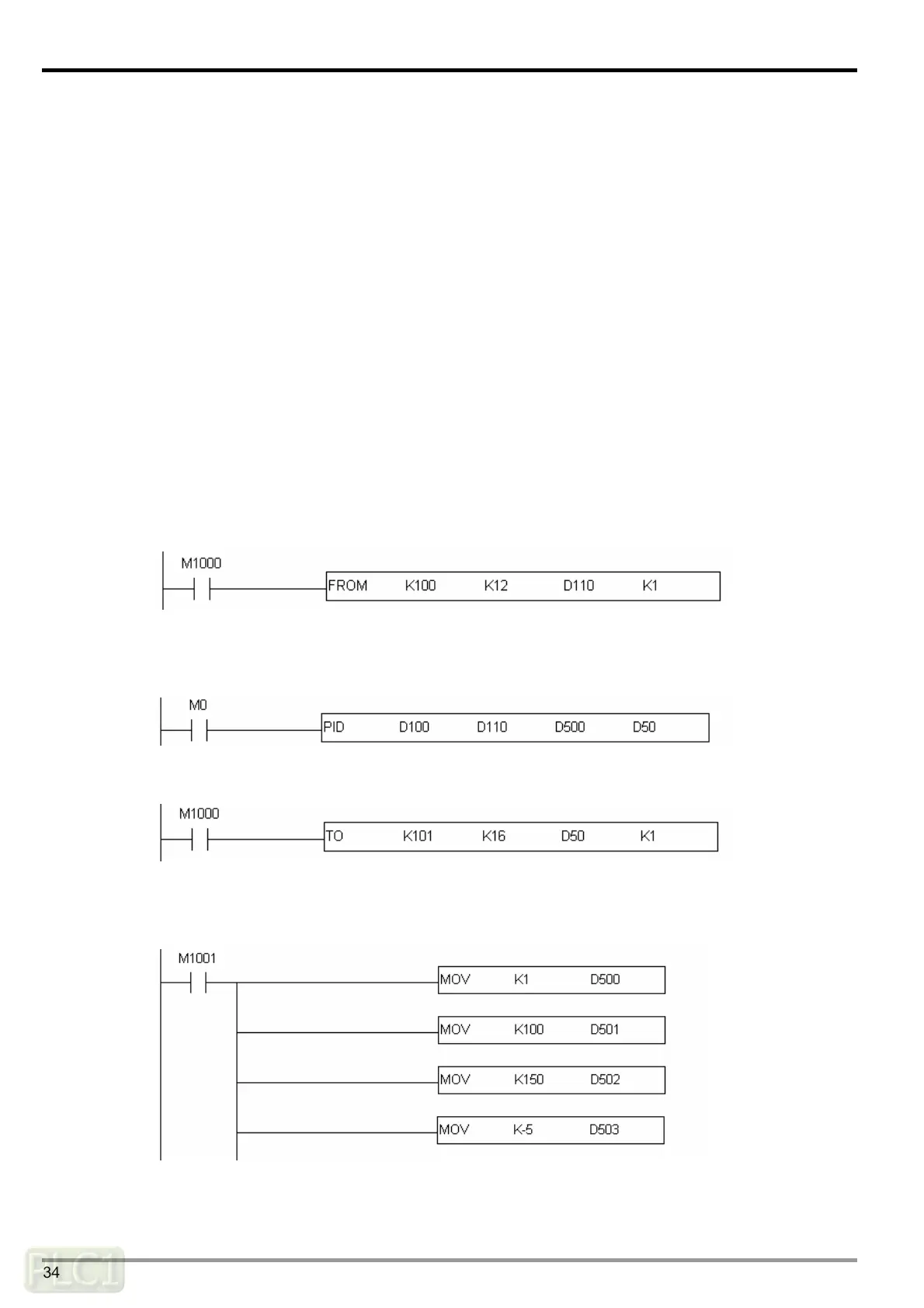
y Steps of PID tuning
1. Read the average value from DVP02LC-SL and store it in D110.
2. For the PID operation: PV = D110, SV = D100, PID parameter = D500. Place the result of PID
operation in D50.
3. Output D50 to CH1 of DVP04DA-SL.
4. Set the PID sampling time to 10 ms. For the parameter settings: KP = D501, KI = D502, KD =
D503.
5. After the tuning, we acquire the best parameters KP = 100, KI = 150 and KP = -5.

 Loading...