DVP-ES3 Series Operation Manual
2-17
*1: If the input signal exceeds the hardware input limit, the module only shows the maximum value. If the
input signal is below the lower limit, it only shows the minimum value.
*2: If the input signal exceeds the hardware input limit, it also exceeds the digital conversion limit and a
conversion limit error appears. For example in the voltage input mode (-10 V to +10 V), when the input
signal is 10.15 V, exceeding the hardware upper limit, it also exceeds the conversion upper limit. The
module uses the upper limit value (32387) as the input signal and a conversion limit error appears.
*3: If an input signal exceeds the absolute range, it might damage the channel.
DVP02DA-E2/DVP04DA-E2
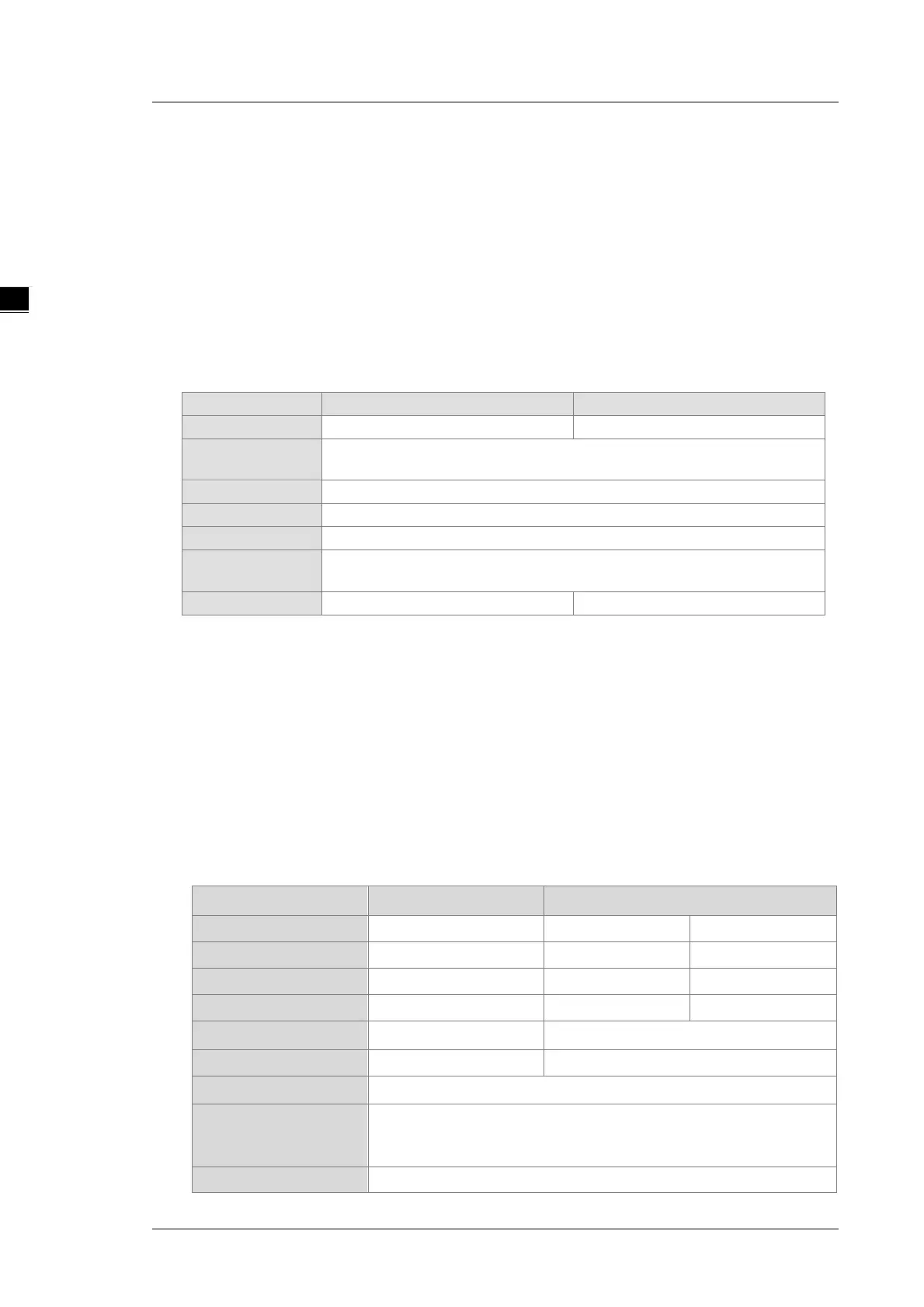
Electrical specifications
Analog-to-digital
Voltage output/Current output
24 VDC (20.4 VDC–28.8 VDC) (-15% to +20%)
Removable terminal block (distance to the terminal is 5 mm)
Short cicuit
1
Yes
*1: The module is with short circuit protection, but if the duration of a short circuit is too long, it can cause
circuit damage. Current output can be open circuit.
Things to note when connecting the module to a CPU PLC module:
1. Up to 8 modules can be connected to a CPU PLC module.
2. The connected module is numbered automatically from 0 (nearest to the CPU PLC module) to 7
(furthest away from the CPU PLC module).
3. The connected modules do NOT take up any digital I/O points.
Functional specifications
Digital/analog module Voltage output Current output
Rated output range
-10 V ~ 10V 0 ~ 20 mA 4 mA ~ 20 mA
Digital conversion range
-32,000 ~ +32,000 0 ~ +32,000 0 ~ +32,000
Digital conversion limit
-32,768 ~ +32,767 0 ~ +32,767 -6,400 ~ +32,767
Hardware resolution
14-bit 14-bit 14-bit
Maximum output current
5 mA
-
Load impedance
1K Ω ~ 2M Ω 0 ~ 500 Ω
Output impedance
0.5 Ω or lower
Overall Accuracy
25° C/77° F: The allowed error range is ±0.5% of full scale.
0° C to 55° C/-32° F to 131° F: The allowed error range is ±1% of full
Digital data format
16-bit two’s complement number
 Loading...


