ComponentNO. NO.
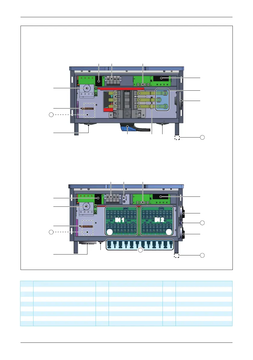
2” cable opening for AC
2½” cable opening for AC
½” cable opening for DC grounding
DC terminal
DC switch
Component
DC switch for IN2
9
10
14
NO. Component
Type II DC SPD
Internal AC terminal
16
17
21
Communication port
22
Grounding (M6 threaded stud)
23
External ground bar location
1
2
Fuse holder type DC IN1
11
Internal DC terminal
18
3
Fuse holder type DC IN212
Wiring box fan
19
4
DC switch for IN1
13
20
MC4 connectors (18 pairs)
5
6
AC switch
2” cable opening for DC
2½” cable opening for DC
DC grounding bar
AC grounding bar
Type II AC SPD
15
7
8
Table 2-3: Wiring box layout description
⑪ ⑫⑪ ⑫
IN 1
IN 2
IN 1
IN 2
-121 Model WB (Without RSD)
-122 Model WB
20
⑬
⑭
⑯
22
23
⑰ ⑱⑲
②
⑥
⑮
⑦
③
21
①
⑤
⑨
⑯
⑦ ④
⑥
⑰
⑱
23
⑮
⑩
⑧
21
Figure 2-7: Wiring box layouts for 121(Without RSD)&122 models
23
Introduction
 Loading...


