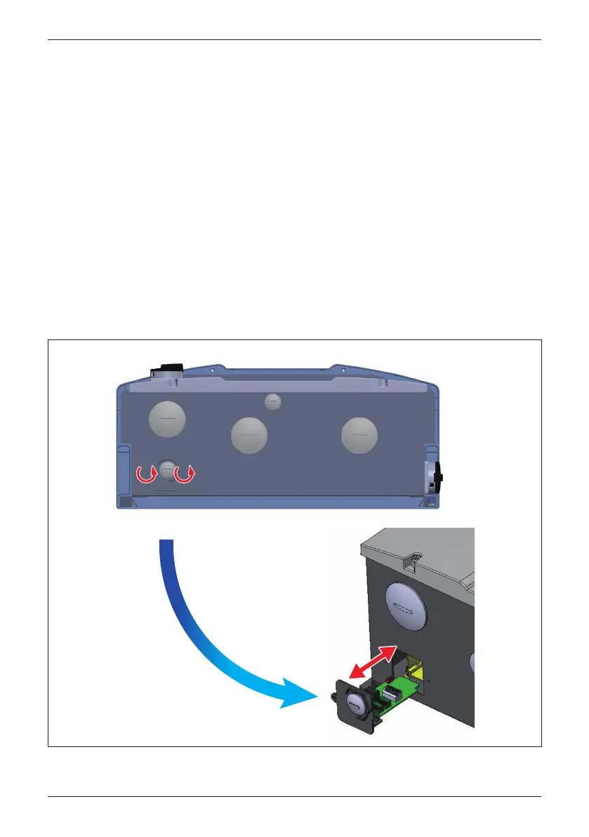
The communication module consists of an assembly with a PCB and a plastic
carrier. It is located in a slot through the bottom of the wiring box chassis.
It is accessed from the bottom exterior of the wiring box. The carrier is secured
to the chassis by two self-retaining screws. See Figure 3-36.
To access the communication module, loosen the two self-retaining screws to
loosen the carrier from the chassis. Once loosened completely, the card/carrier
module can be withdrawn from the wiring box chassis by gently pulling the
carrier straight out from the chassis.
After pulling the desired signal cable(s) through the wiring gland provided or a
connected conduit, and connected electrically as shown in the following sections,
the module can be reinstalled by reversing the above directions. Ensure the
assembly is oriented into the chassis so as to allow the edge connector to
engage properly.
3.5.1 Accessing the Communication Module
Figure 3-36: Location and access to Communication Module
* Screw torque required for assembling:
7 lbf-in (0.8N•m)
58
Installation