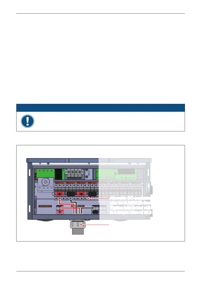
Figure 3-24: Location and string wiring to DC fuse holders for M80/60U_120
(shown for MPPT 1)
--
--
++
++
--
++
M80/60U_120
EMT
2” trade size chassis access,
1 per MPPT, 2 pl total,
for connection of DC conduits
Allowable DC conductor
size 14~8 AWG (2~8mm
2
)
Tighten fuse holder screws
to a torque value of 24.8 lbf-in (2.8 N•m)
Allowable DC conductor
size 14~8 AWG (2~8mm
2
)
Tighten fuse holder screws
to a torque value of 24.8 lbf-in (2.8 N•m)
- Ensure all fuse holder terminals are tightened to the specified torque value of
24.8 lbf-in (2.8 N•m).
ATTENTION
• Ensure the DC conductors used are Cu and sized to the correct ampacity per
NEC or other local code
• Strip off all wires for 14 mm [0.55in].
• The cross-sectional area for each DC conductor is 14~8 AWG.
• Ensure the fuse holder terminal clamp is open
• Ensure correct conductor is connected to the correct fuse holder.
• Tighten each individual screw terminal screw to a torque value of 24.8 lbf-in
(2.8 N•m).
• Two 2” chassis access holes (KOs), one per MPPT can be utilized to connect
conduits from PV array DC wiring into the inverter, as shown in Figure 3-24.
Please read the following instructions for connecting DC terminals (M80/60U_120) :
3.4.1 DC Wiring Installation for M80/60U_120 models
48
Installation