13
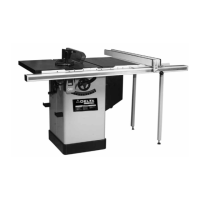
HOW TO ATTACH THE RIP FENCE GUIDE RAIL
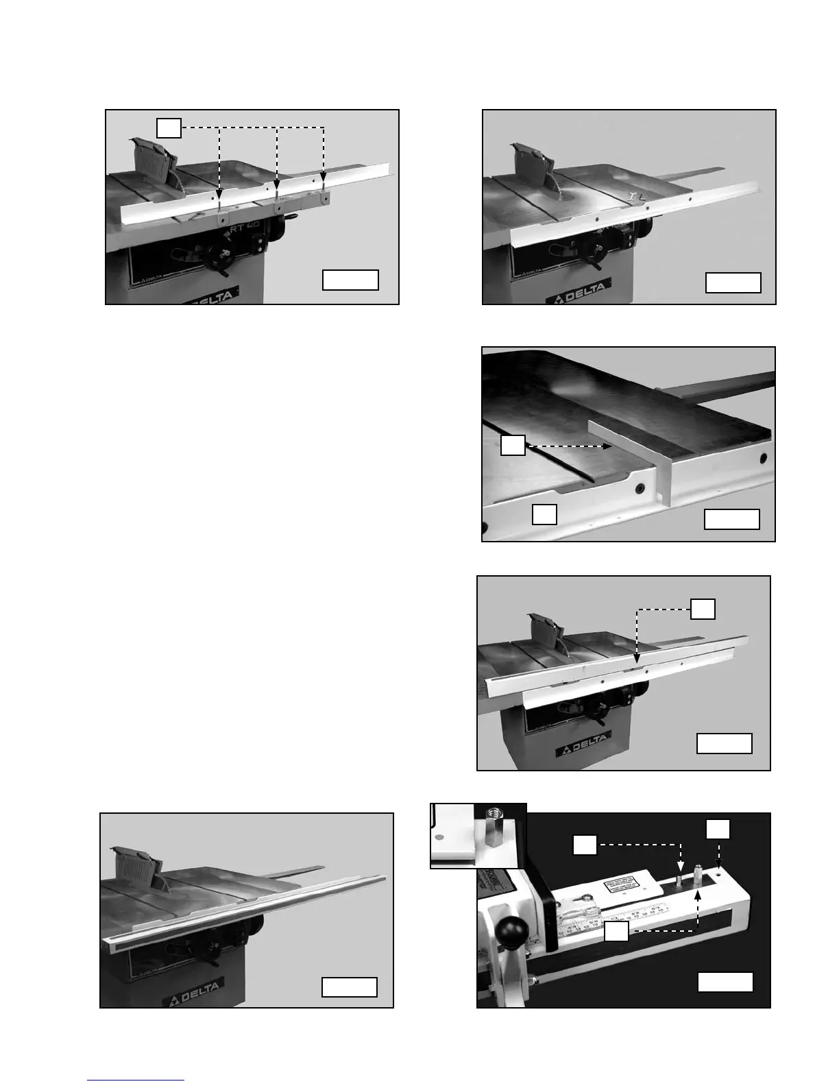
1. Use three (3) 1/2-13 X 2" flat-head bolts, flat washers, lockwashers, and hex nuts (A) Fig. 21 to attach the guide rail
to the front of the saw table (Fig. 22). Loosely tighten with the supplied hex wrench for further adjustment.
2. Use the template (A) Fig. 23 that is supplied with the
fence system to check and adjust the level of the
front rail (B) to both ends of the saw table. Tighten
the guide rail hardware securely.
NOTE: Do NOT level the rail with the extension wing. Use
the saw table.
3. Place the guide tube (A) Fig. 24 on the saw table.
Align the nine (9) threaded holes with the holes in the
front ledge.
4. Position the guide tube on the front rail. Secure the
guide tube with nine (9) 1/2" hex-head bolts and
lockwashers.
6. Insert a bolt (A ) Fig. 26 up through the hole (B ) at
the extreme right end of the guide tube. Thread the
retaining nut (C ) on the bolt (see the inset - Fig. 26)
NOTE: This retaining nut prevents the fence from falling
off the end of the guide rail.
IMPORTANT: Before applying power to the saw, en-
sure that the rip fence is parallel to the miter gauge
slot. Refer to the section "HOW TO OPERATE AND
ADJUST THE RIP FENCE".
Fig. 21
Fig. 22
Fig. 23
Fig. 24
Fig. 25
Fig. 26
A
A
B
A
A
B
C
5. Place the rip fence on the guide rail.