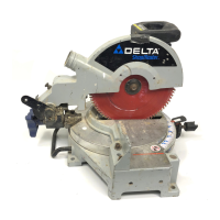
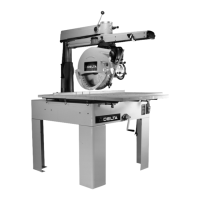
The device described in this manual is a Delta Long Arm Radial Saw, available in 14", 16", and 18" blade sizes. It is designed for various woodworking operations, including cross-cutting, miter cutting, compound miter cutting, ripping, out-ripping, and in-ripping. The manual covers models 33-400, 33-401, 33-402, 33-403, 33-410, 33-411, 33-412, 33-413, 33-420, 33-421, 33-422, and 33-423.
Function Description
The Delta Long Arm Radial Saw features a totally enclosed, fan-cooled motor with an electro-mechanical blade brake. Key components include a blade guard with an anti-kickback attachment, a retractable leaf guard, a cutterhead return attachment, a cuttinghead clamp knob, an adjustable crosscut stop, and steel legs.
The saw's operation relies on several adjustable controls:
- Track-Arm Clamp Handle (A): Controls the swing of the track-arm for miter cutting operations, locking it at any angle within its 180° rotation. It stops at 0° and 45° positions (right and left) and requires pulling out the Track-Arm Index Knob (B) to move past these points.
- Track-Arm Index Knob (B): Locates the 0° and 45° miter positions.
- Yoke Index Knob (C): Locates each 90° position of the yoke for ripping or cross-cutting. The Yoke Clamp Handle (D) must be loose to rotate the yoke.
- Yoke Clamp Handle (D): Must be loose when rotating the yoke to rip or cross-cut positions.
- Anti-Kickback Device (E): Used during ripping. The yoke is positioned parallel to the fence, and the rear of the blade guard is lowered to almost touch the workpiece. The anti-kickback rod is then lowered so its fingers catch and hold the workpiece, preventing kickback. Ripping should never be performed from the anti-kickback end of the blade guard.
- Elevating Crank Handle (F): Controls the depth of cut by raising or lowering the over-arm.
- Cuttinghead Clamp Knob (G): Locks the cuttinghead at any position on the track-arm. It must be tight for ripping operations.
- Cross-Cut Stop (H): Prevents unnecessary travel of the cuttinghead on the track-arm, useful for repetitive operations. It clamps to the side of the track-arm to stop travel as the blade cuts through the workpiece.
- Bevel Index Knob (J): Locates 0°, 45°, and 90° positions for bevel cutting. The Bevel Clamp Handle (K) must be loose to tilt the motor.
- Bevel Clamp Handle (K): Controls the tilt of the motor for bevel cutting, locking it at any desired angle on the bevel scale.
- Table Clamp Knobs (L): Allow quick adjustment of the fence position.
- Cuttinghead Return Attachment (M): Automatically returns the cuttinghead to the rear of the track-arm after a cut.
Important Technical Specifications
- Motor: Wired for 230V, 60HZ alternating current. The horsepower rating, dual voltage capability (230/460 volts), and single or three-phase configuration are specified on the motor's nameplate.
- Power Connection: Not supplied with a power cord. Requires permanent connection to the building's electrical system by a qualified electrician, conforming to National Electric Code and local codes. Extension cords are not to be used.
- Circuit Requirements: A separate electrical circuit, not less than #12 wire, protected with a 20 Amp time lag fuse, is recommended.
- Blade Brake: Electro-mechanical, designed to stop the blade within a maximum of one second per one inch of blade diameter. The air gap for the brake must be maintained between .008" and .012".
- Blade Sizes: Available in 14", 16", and 18".
Usage Features
- Cross-Cutting: The track arm is indexed at 0° and clamped. The fence is clamped between table boards, with the blade to the left and behind the fence. The workpiece is placed against the fence, and the blade is lowered to lightly cut the table. The operator pulls the blade through the work and returns it to the starting position. For material over 1" thick, the fence must be positioned immediately behind the fixed front table board.
- Miter Cutting: Similar to cross-cutting, but the track arm is positioned at a desired angle (up to 45° right or left) on the miter scale before clamping.
- Compound Miter Cutting: Combines miter cutting with bevel cutting. The saw blade is tilted to a desired angle on the bevel scale before clamping.
- Ripping: The track arm is clamped at 0° on the miter scale, and the yoke is positioned parallel to the fence. The blade guard is lowered on the in-feed side to act as a holddown. The splitter and anti-kickback fingers are adjusted. For narrow work (less than 4 inches wide), a push stick is required. The workpiece must have a straight edge to follow the fence. The cutting-head clamp knob must be securely tightened.
- Out-Ripping: Yoke clamped at a right angle to the track arm, with the blade guard facing the front. The cutting-head is positioned on the out-rip scale. Workpiece is fed from the left side.
- In-Ripping: Yoke clamped at a right angle to the track arm, with the blade guard facing the rear. The cutting-head is positioned on the in-rip scale. Workpiece is fed from the right side.
- Safety: The machine includes a locking switch to prevent unauthorized use, requiring a padlock. Users are advised to wear eye and hearing protection, proper apparel, and use guards. Workpieces should be secured with clamps. The machine should never be forced, and the workpiece should be fed against the direction of blade rotation.
Maintenance Features
- Cleaning: Periodically blow out air passages with dry compressed air. Plastic parts should be cleaned with a soft damp cloth; solvents are not to be used.
- Lubrication: Apply household floor paste wax to the machine table and extension table weekly.
- Rust Protection: For cast iron tables, use WD-40, a Scotch-Brite™ Blending Hand Pad, a pushblock, degreaser, and TopCote® Aerosol. Apply WD-40, polish with the pad, degrease, and then apply TopCote®.
- Adjusting Table Top Parallel to Track-Arm: Requires moving the motor and cuttinghead to a vertical position, positioning the saw arbor in the center of the front table board, securing the track-arm, and tightening the cuttinghead clamp knob. A spanner wrench is used as a feeler gauge to adjust the track-arm height via the elevating handle. Further adjustments involve checking the table at various points and adjusting nuts to raise or lower the table.
- Blade Guard and Anti-Kickback Device Adjustment: Involves loosening set screws, removing the arbor nut and outer blade flange, installing the blade with teeth pointing downward, and reassembling the flange and nut. The arbor nut is tightened using a 1-1/16" wrench on the arbor flats and a 1-5/8" box end spanner wrench on the nut. The leaf guard and anti-kickback rod are then assembled and adjusted.
- Cutterhead Return Spring Adjustment: Requires removing the fence, returning the cuttinghead to the rear, rotating the track arm 90 degrees, removing a screw from the yoke assembly, and assembling the reel to the yoke. Tension is adjusted by turning the adjustment dial clockwise to increase tension or pulling back the cable tension release knob to decrease tension.
- Adjusting Blade Square with Table Top: Involves removing the blade guard, placing the saw blade in a cut-off position over the fixed table, and using a square against the blade and table. The bevel clamp handle and screws are loosened to tilt the motor assembly until the square is flush, then retightened. If needed, the scale plate is removed, and socket head screws are loosened to rotate the motor for adjustment.
- Adjusting Bevel Clamp Handle: If the handle doesn't securely lock the motor, position the motor in a bevel cutting position, place the handle in the locked position, loosen a nut, and tighten a bolt until the motor is locked.
- Adjusting Track-Arm Clamp Handle: If the handle needs to be moved beyond its usual position to clamp the track-arm, move the handle to the rear, loosen a set screw, remove the handle, reposition it on the stud, and move it to the rear until the track-arm is locked, then tighten the set screw.
- Adjusting Saw Travel Square with Fence ("Micro-Set" Miter Stops): Involves placing a square against the fence and lowering the cuttinghead. If the blade does not travel parallel, the cover plate is removed, the center cap screw is loosened, and a thin wooden wedge is inserted to loosen the tapered plug. The clamp handle and hex nut are adjusted to turn the track slightly. After adjustment, the clamp handle and center cap screw are tightened, and the pointer is adjusted to 0 degrees.
- Removing "Heeling" in Saw Cut: Cross-cut a board and check for saw teeth marks. If marks appear on the right, shift the blade toward the left by loosening the yoke clamp handle and screws, then turning the yoke counter-clockwise. If marks appear on the left, turn the yoke clockwise. Retighten all components after adjustment.
- Checking and Adjusting Automatic Brake: Remove four screws and the fan cover from the motor. Measure the air gap (D) which should be between .008" and .012". If adjustment is needed, turn the lock nut until the proper gap of .010" is attained. Replace the fan cover.
- Auxiliary Table Board Facing: Recommended to prevent repeated cutting into the table surface. A 1/4" plywood or particle board facing can be cut to cover the table boards in front of the fence, butted against the fence, and fastened with small brads or finish nails.
- Table Extension: For extensions longer than 24 inches, a sturdy outrigger support or securing the stand/bench to the floor is required.