EasyManua.ls Logo

Delta 28-195 - User Manual

Delta 28-195
21 pages
Print Icon
To Next Page IconTo Next Page
Loading...
INSTRUCTION MANUAL
10" Band Saw
(Model 28-195)
PART NO. 902127 (0112)
Copyright © 2001 Delta Machinery
ESPAÑOL: PÁGINA 23
To learn more about DELTA MACHINERY
visit our website at: www.deltamachinery.com.
For Parts, Service, Warranty or other Assistance,
please call
1-800-223-7278 (In Canada call 1-800-463-3582).
Question and Answer IconNeed help?

Do you have a question about the Delta 28-195 and is the answer not in the manual?

Summary

General Safety Rules

Additional Safety Rules for Band Saws

Essential safety guidelines specific to operating band saws.

Power and Grounding

Grounding Instructions

Crucial steps for grounding the machine to prevent electric shock hazards.

Operating Instructions

Assembly Instructions

Operating Controls and Adjustments

Blade Tension and Tracking

Adjusting blade tension and ensuring the blade tracks correctly on wheels.

Upper Blade Guides and Support Bearing

Setting the upper blade guides and support bearing for optimal performance.

Lower Blade Guides and Support Bearing

Setting the lower blade guides and support bearing for optimal performance.

Overview

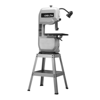
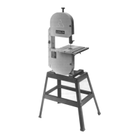
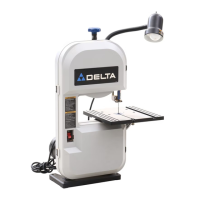
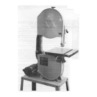
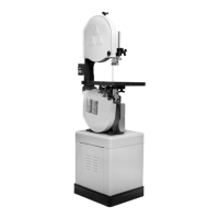
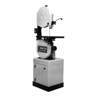
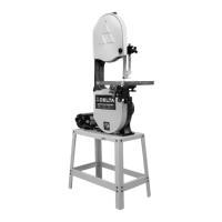
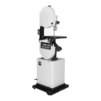
The Delta Model 28-195 is a 10" Band Saw designed for woodworking applications. It features a powerful 1/2 HP, ball-bearing motor, ensuring smooth performance and extended life. The machine is supplied with a sturdy steel stand, providing heavy-duty support and a comfortable work height.

Technical Specifications:

  • Model: 28-195
  • Blade Size: 72-1/2 inches long
  • Motor: 1/2 HP, ball-bearing
  • Electrical Requirements: 120 volt, 60 Hz alternating current. A dedicated #12 wire circuit protected by a 20 Amp time lag fuse is recommended.
  • Table Tilt: Can be tilted 48 degrees to the right and approximately 3 degrees to the left.
  • Dust Chute: 2-1/4" I.D. opening for connection to a standard shop vacuum or dust collector.

Function Description:

The band saw is designed for cutting wood and similar materials. It can perform straight cuts, rip cuts, and curve cutting. The machine's design emphasizes user safety and operational precision.

Usage Features:

  • Assembly: The manual provides detailed instructions for assembling the stand, mounting the band saw to the stand, attaching the table to the trunnions, inserting the table insert, and assembling the lamp.
  • Starting and Stopping: The ON/OFF switch is located on the front side of the band saw. Moving the switch up turns the saw ON, and moving it down turns it OFF.
  • Locking Switch: For safety and to prevent unauthorized use, the switch can be locked in the "OFF" position by pulling out the switch toggle. The saw cannot be restarted without reinserting the toggle.
  • Blade Tension Adjustment: A tension adjustment knob allows users to increase or decrease blade tension. Graduations (1 through 5) serve as reference points for proper tensioning based on blade width. Wider blades require more tension. It is good practice to release tension when the saw is not in use to prolong blade life and prevent blade set.
  • Blade Tracking: For accurate work and maximum blade life, the blade must be centered on the upper band saw wheel. Tracking is adjusted by loosening a lock nut and turning a tracking adjusting nut while slowly rotating the upper wheel by hand. The saw should NEVER be run to track the blade.
  • Upper Blade Guide Assembly Adjustment: The upper blade guide assembly should be set approximately 1/8" above or as close as possible to the top surface of the workpiece. This is adjusted by loosening a lock knob and rotating an adjusting knob to the desired height.
  • Blade Guide and Support Bearing Adjustment (Upper and Lower): Blade guides prevent the blade from twisting during operation and should be adjusted after tensioning and tracking. The guides should be moved as close as possible to the blade sides without pinching, with their front edges just behind the "gullets" of the blade teeth. The blade support bearing supports the back of the blade during cutting and prevents it from being pushed too far back. It should be set about 1/64" behind the blade and overlap the outside diameter of the ball bearing by approximately 1/8".
  • Table Tilting: The table can be tilted to various angles. A lock handle is used to secure the table at the desired tilt, indicated by a scale and pointer.
  • Table Positive Stops: Positive stops are provided for 90 and 45-degree angles to the blade. These can be checked and adjusted using a square and adjusting screws.
  • Changing Blades: Blade changes require disconnecting the machine from the power source, opening wheel guards, removing the blade guard, releasing blade tension, removing the table alignment screw and insert, slipping the blade off the wheels, and then installing the new blade. New blades should have teeth pointing down towards the table.
  • Belt Tension Adjustment: The drive belt tension is correct when there is approximately 1/4" deflection in the center span with light finger pressure. Adjustment involves loosening screws and rotating the motor.
  • Miter Gage: A miter gage is supplied for making angled cuts, adjustable up to 45 degrees right and left. It can be rotated 180 degrees for increased workpiece support.
  • Rip Fence (Accessory 28-196): An optional rip fence can be used for straight cutting, moved along the table surface by loosening and tightening a lock lever.
  • Cutting Curves: When cutting curves, the stock should be turned carefully to avoid twisting the blade. For abrupt curves, a narrower blade or a blade with more set may be needed. It is safer to saw out through waste material rather than withdraw the stock from the blade during an uncompleted cut.
  • Blade Selection: Always use the widest blade possible for the task. Narrow blades are for small, abrupt curves and fine work. Delta supplies blades in widths of 1/8, 1/4, 3/8, and 1/2 inches for wood and similar materials.

Maintenance Features:

  • Cleaning: Unpainted surfaces should be cleaned of protective coating with a soft cloth moistened with kerosene and then covered with a good quality household floor paste wax. The blade area, wheels, and tires should be kept free of sawdust, gum, and pitch accumulation.
  • Blade Care: Keep saw blades sharp and free from gum and pitch. Do not over-tension blades, as this can cause breakage. Release blade tension when not in use.
  • Tire Brush: A tire brush is provided on the lower wheel to keep the blade and tires clean. It can be adjusted by loosening its mounting hardware.
  • Wrench Storage: The supplied hex wrench can be stored inside the wheel cover.
  • General Safety: Always wear eye protection, keep guards in place, remove adjusting keys/wrenches before starting, keep the work area clean, and disconnect the machine from the power source before servicing or changing accessories. Refer to the general safety rules and additional safety rules for band saws provided in the manual.

Delta 28-195 Specifications

General IconGeneral
BrandDelta
Model28-195
CategorySaw
LanguageEnglish

Related product manuals