Chapter 4 Main Circuit Terminals | VFD-ED
4-2 Main Circuit Terminal Specifications
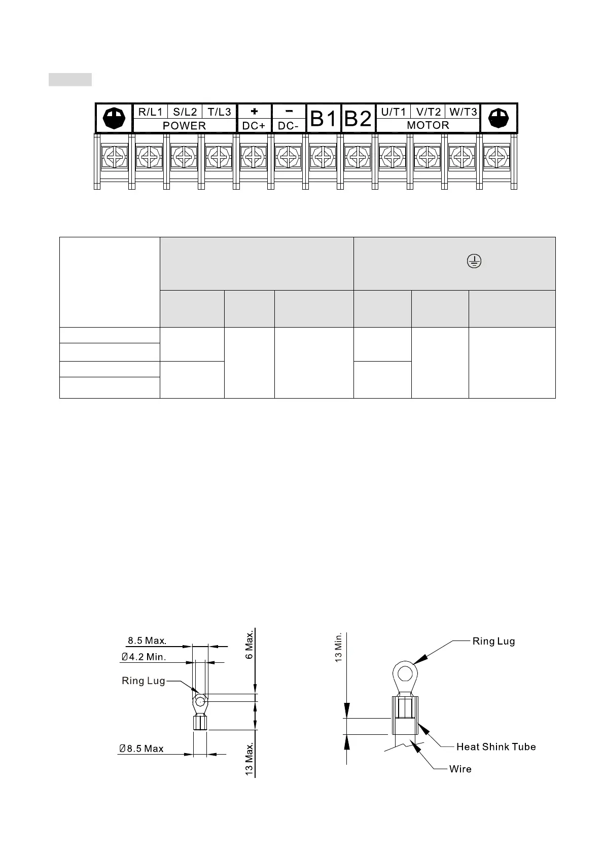
Frame B
Figure 4-5
Model
Main Circuit Terminals
R/L1, S/L2, T/L3, U/T1, V/T2, W/T3,
+(DC+), -(DC-), B1, B2
Terminal
Min. Wire
Gauge
Max. Wire
Gauge
Tightening Torque
Min. Wire
Gauge
Max. Wire
Gauge
Tightening Torque
2.1 mm²
(14 AWG)
5.3 mm²
(10 AWG)
M4
18 kg-cm
(15.6 lb-in.)
(1.7 N-m)
2.1 mm²
5.3 mm²
(10 AWG)
M4
18 kg-cm
(15.6 lb-in.)
VFD040ED43S
VFD037ED21S
3.3 mm²
(12 AWG)
3.3 mm²
(12 AWG)
VFD040ED23S
Table 4-2
For UL installation compliance, select copper wires with voltage rating of 600V and temperature
resistance of 75°C.
Choose terminal wire size as Figure 4-6 shows.
Use insulated heat shrink tubing that is resistant to at least 600V to comply with UL and CSA
regulations (600 V, YDPU2), as Figure 4-7 shows.
If you install at Ta 50°C environment, use copper wires with voltage rating of 600V and
temperature resistance of 75°C or 90°C.
If you install at Ta 50°C above environment, use copper wires with voltage rating of 600V and
temperature resistance of 90°C or above.
To be UL installation compliant, you must use copper wires when installing. The wire gauge is
based on temperature resistance of 75°C, in accordance with UL requirements and
recommendations. Do not reduce the wire gauge when using high-temperature resistant wire.
Figure 4-6 Figure 4-7

 Loading...


