Appendix B. Modbus ProtocolVFD-ED
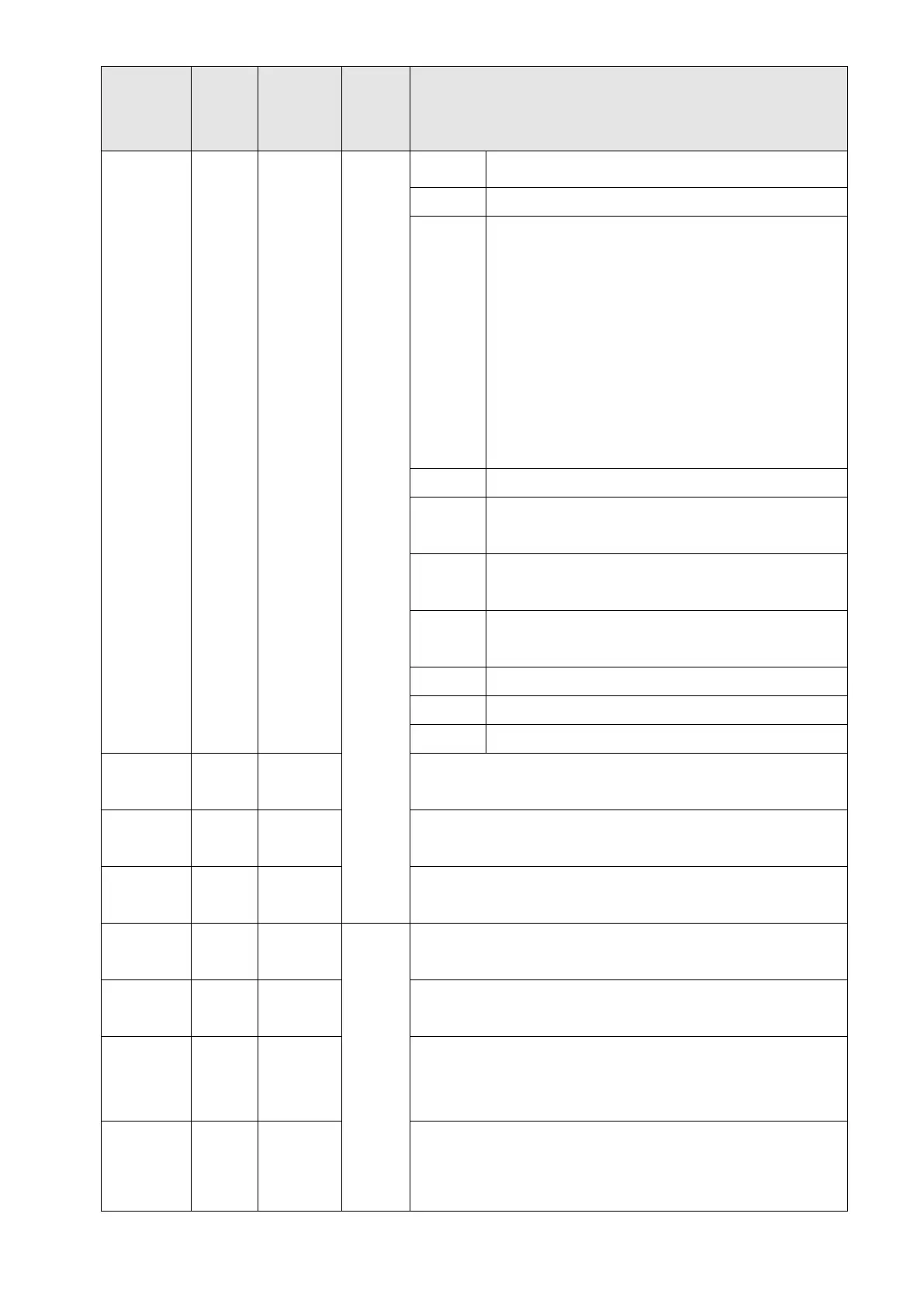
Function
Name
Modbus
Address
Attribute
(Function
Code)
Size Description
(RUN indicator is ON / STOP indicator is OFF)
bit2 1: JOG command
bit4–3
Operation direction
00B: FWD
(REV indicator is OFF / FWD indicator is ON)
01B: from REV to FWD
(REV indicator flashes / FWD indicator is ON)
10B: from FWD to REV
(REV indicator is ON / FWD indicator flashes)
11B: REV
(REV indicator is ON / FWD indicator is OFF)
bit7–5 Reserved
bit8
1: Master frequency controlled by communication
interface
bit9
1: Master frequency controlled by analog / external
terminal signal
bit10
1: Operation command controlled by
communication interface
bit11 1: Parameter locked
bit12 1: Enable copy parameter from keypad
bit15–13 Reserved
Frequency
command
2102H R(03H) Drive’s frequency command (XXX.XX Hz)
Output
frequency
2103H R(03H) Drive’s output frequency (XXX.XX Hz)
Output
current
2104H R(03H)
Drive’s output current (XX.XX A). Decimal places
referred by the high byte of 211F
DC bus
voltage
2105H R(03H)
U16
Drive’s DC bus voltage (XXX.X V)
Output
voltage
2106H R(03H) Drive’s output voltage (XXX.X V)
Multi-step
speed
status
2107H R(03H)
Drive’s current running speed step given by multi-
command (0 is main speed)
Multi-
function
display
2116H R(03H)
Display the low word value (Pr.00-04) of user-
value is low 16 bits data.

 Loading...


