5
VFD-B Series
DELTA ELECTRONICS, INC. ALL RIGHTS RESERVED
5-69
10 - 04
Derivative Control (D)
Factory Setting: 0.00
Settings 0.00 to 1.00 sec
This parameter specifies derivative control (rate of change of the input) and associated
gain (D). With this parameter set to 1, the PID output is equal to differential time X
(present deviation − previous deviation). It increases the response speed but it may cause
over-compensation.
10 - 05
Upper Bound for Integral Control
Factory Setting: 100
Settings 00 to 100 % Unit: 1 %
This parameter defines an upper bound or limit for the integral gain (I) and therefore limits
the Master Frequency.
The formula is: Integral upper bound = Maximum Output Frequency (Pr.01-00) x
(Pr.10-05). This parameter can limit the Maximum Output Frequency
10 - 06
Primary Delay Filter Time
Factory Setting: 0.0
Settings 0.0 to 2.5 sec Unit: 0.1 sec
(1) To avoid amplification of measurement noise in the controller output, a derivative
digital filter is inserted. This filter helps in smoothing oscillations.
(2) When Pr.02-01 is set to 01 or 02, the set point (Master Frequency) for PID control is
obtained from the AVI external terminal (0 to +10V) or from multi-step speed. When
Pr.02-01 is set to 00, the set point is obtained from the keypad.
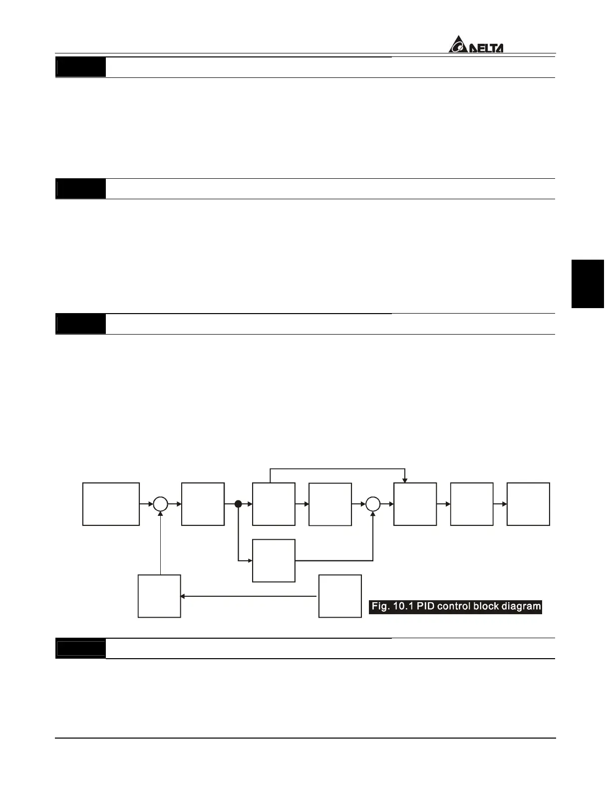
The complete PID diagram is the following:
P
10-02
I
10-03
D
10-04
10-05
10-01
10-07
10-06
10-00
+
-
+
+
+
Setpoint
Input Freq.
Gain
PID
feedback
Integral
gain
limit
Output
Freq.
Limit
Digital
filter
Freq.
Command
10 - 07
PID Output Frequency Limit
Factory Setting: 100
Settings 00 to 110 % Unit: 1%
This parameter defines the percentage of output frequency limit during the PID control.
The formula is Output Frequency Limit = Maximum Output Frequency (Pr.01-00) X
Pr.10-07 %. This parameter will limit the Maximum Output Frequency.
 Loading...