5
VFD-B Series
DELTA ELECTRONICS, INC. ALL RIGHTS RESERVED
5-65
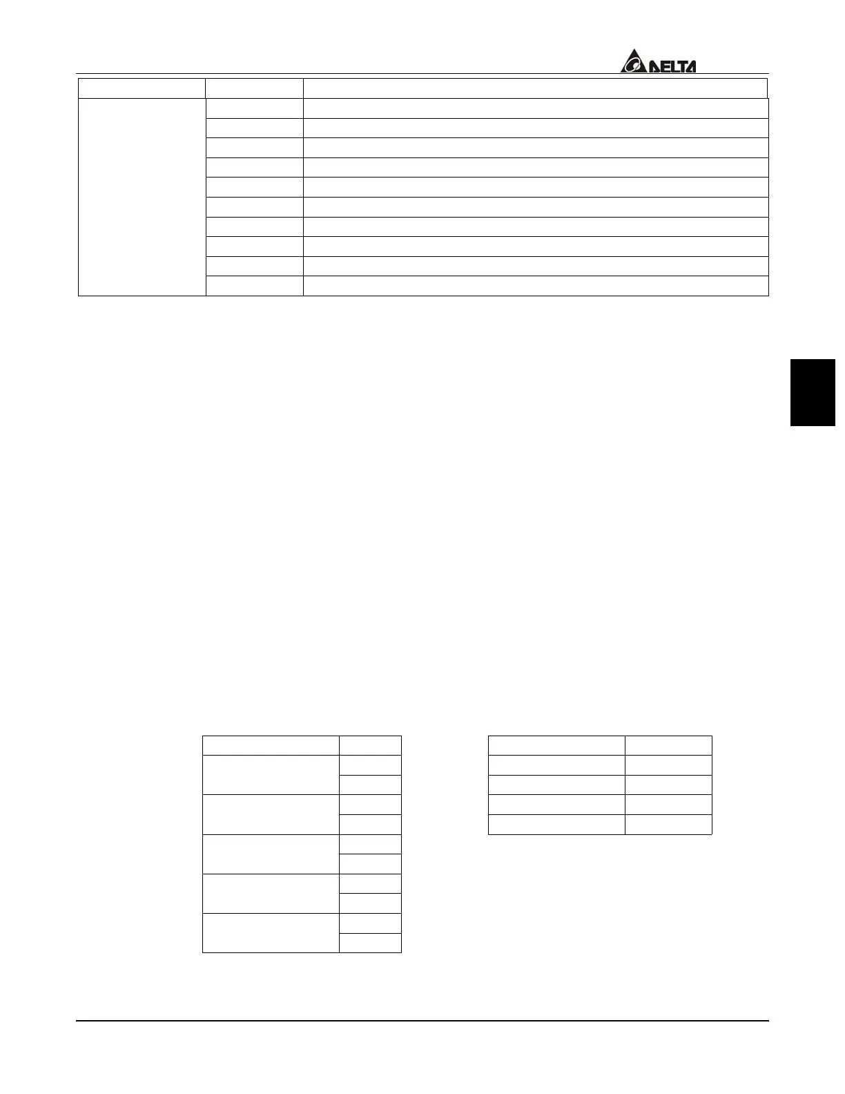
Content Address Function
210DH PG pulse (low byte) /unit time (Pr.10-15)
210EH PG pulse (high byte) /unit time (Pr.10-15)
210FH Output power (KW)
2110H Reserved
2200H Feedback Signal (XXX.XX %)
2201H User-defined (Low word)
2202H User-defined (High word)
2203H AVI analog input (XXX.XX %)
2204H ACI analog input (XXX.XX %)
2205H AUI analog input (XXX.XX %)
3.6 Exception response:
The AC drive is expected to return a normal response after receiving command
messages from the master device. The following depicts the conditions that no
normal response is replied to the master device.
The AC drive does not receive the messages due to a communication error; thus, the
AC drive has no response. The master device will eventually process a timeout
condition.
The AC drive receives the messages without a communication error, but cannot
handle it, an exception response will return to the master device and an error
message “CExx” will display on the keypad of AC drive. The xx of “CExx” is a
decimal code equal to the exception code that will describe below.
In the exception response, the most significant bit of the original command code is set
to 1, and an exception code explains the condition that caused the exception is
returned. An example of exception response of command code 06H and exception
code 02H:
ASCII mode:
RTU mode:
STX ‘:’ ADR 01H
‘0’ CMD 86H ADR 1
ADR 0
‘1’ Exception code 02H
‘8’ CRC CHK Low C3H CMD 1
CMD 0
‘6’ CRC CHK High A1H
‘0’
Error code
‘2’
‘7’ LRC CHK 1
LRC CHK 0
‘7’
CR END 1
END 0
LF
The explanation of error codes:
 Loading...