Chapter 16 PLC Function ApplicationsMS300
703
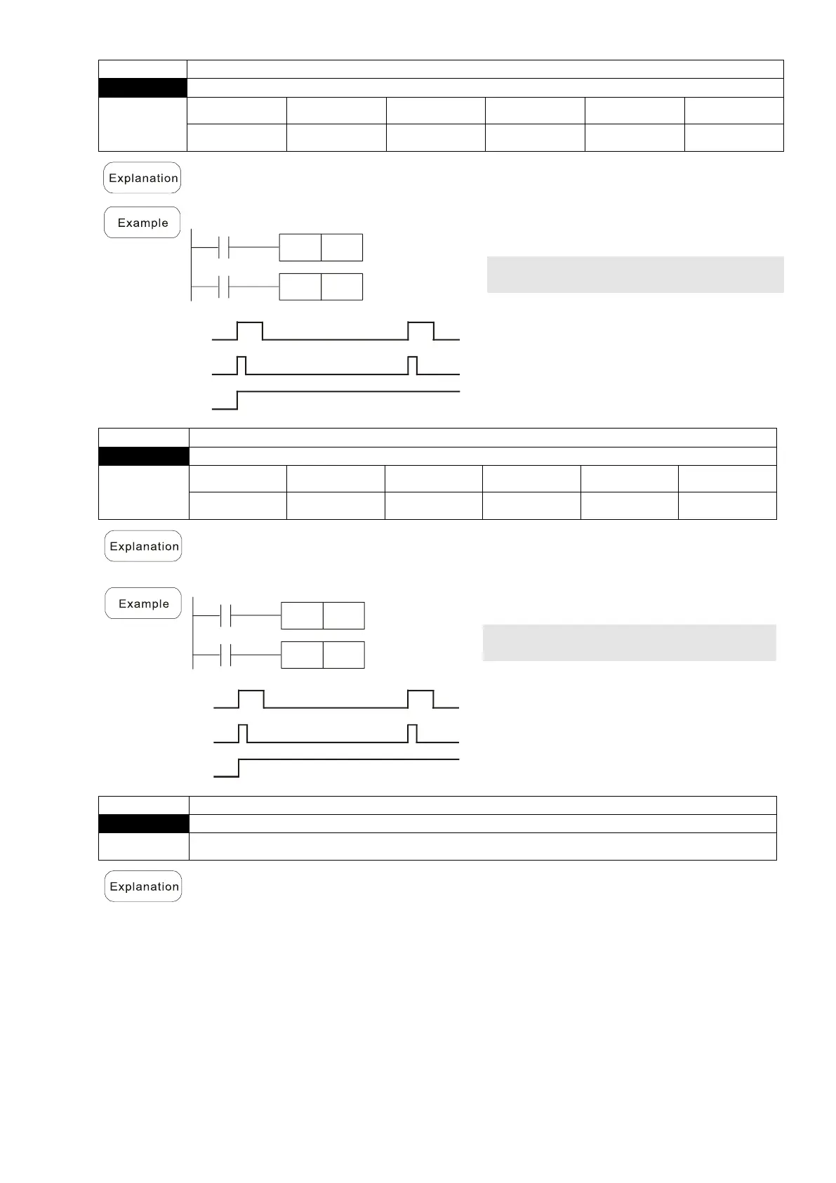
Upper differential output
Upper differential output command: when X0 switches from OFF to ON (rising edge-
triggered), the PLS command is executed, and M0 sends one pulse with the pulse
length consisting of one scanning period.
X0
M0
Y0
Time for one scan cycle
M0 Upper differential
output
Lower differential output
Lower differential output command: when X0 switches from ON to OFF (falling edge-
triggered), the PLF command is executed, and M0 sends one pulse with the pulse
length consisting of one scanning period.
X0
M0
Y0
Time for one scan cycle
M0 Lower differential
output
An END command must be added to the end of a ladder diagram program or
command program. The PLC scans the program from address 0 to the END
command, and then returns to address 0 and begins scanning again.
 Loading...