Chapter 16 PLC Function Applications│CP2000
16-3
16-2 Notes before PLC use
1. The PLC has a preset communications format of 7, N, 2, 9600, with node 2; the PLC node can
be changed in Pr.09-35, but this address may not be the same as the drive's address setting of
Pr.09-00.
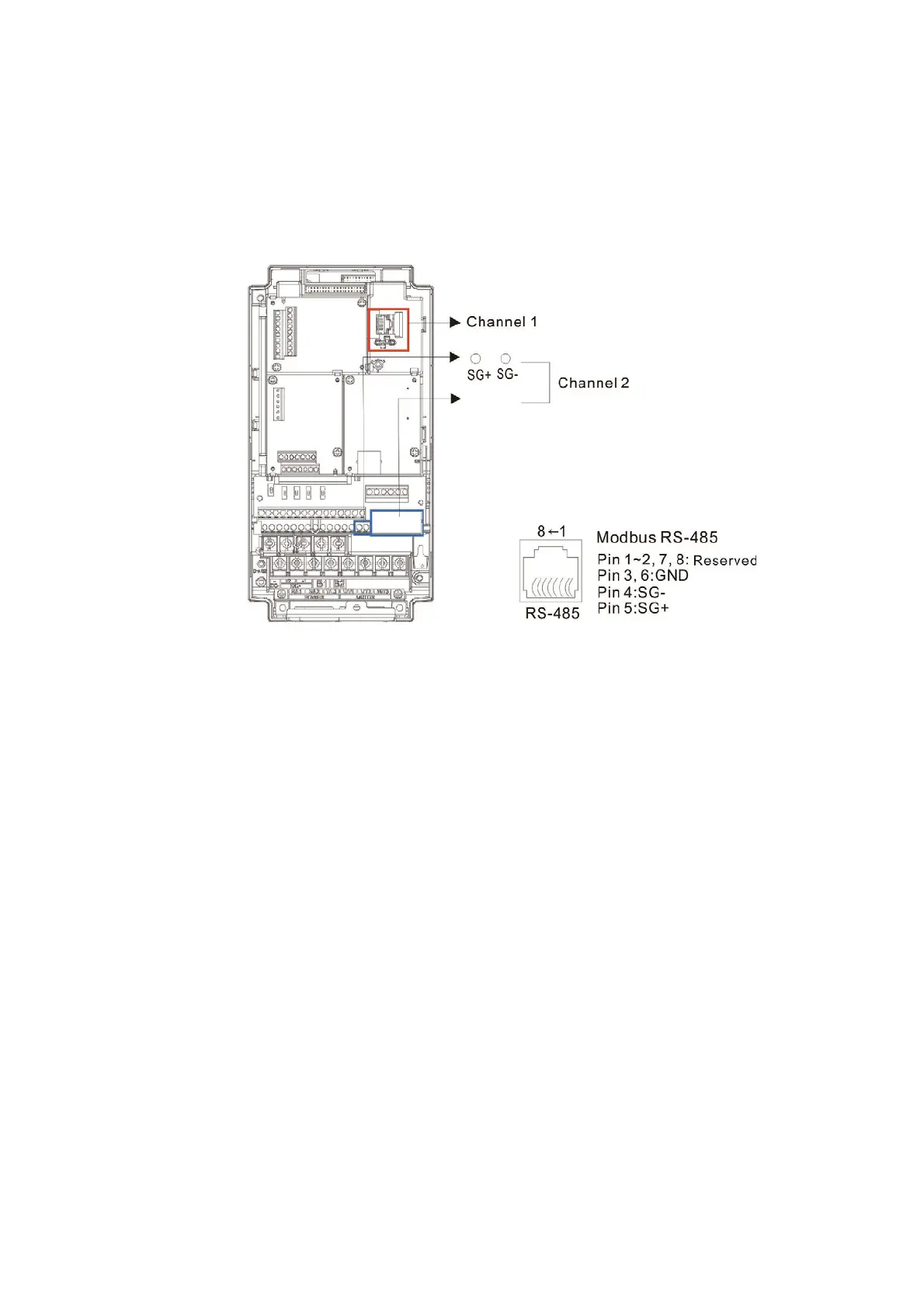
2. The CP2000 provides 2 communications serial ports that can be used to download PLC
programs (see figure below). Channel 1 has a fixed communications format of 19200, 8, N, 2
RTU.
3. The client can simultaneously access data from the converter and internal PLC, which is
performed through identification of the node. For instance, if the converter node is 1 and the
internal PLC node is 2, then the client command will be
01 (node) 03 (read) 0400 (address) 0001 (1 data item), indicating that it must read the data in
converter Pr.04-00.
02 (node) 03 (read) 0400 (address) 0001 (1 data item), indicating that it must read the data in
internal PLC X0
4. The PLC program will be disabled when uploading/ downloading programs.
5. Please note when using WPR commands to write in parameters, values may be modified up to
a maximum of 10
9
times, otherwise a memory write error will occur. The calculation of
modifications is based on whether the entered value has been changed. If the entered value is
left unchanged, the modifications will not increase afterwards. But if the entered value is
different from before, the number of modifications will increase by one. Those parameters listed
below are exceptions, please proceed to the next page for details:
Pr.00-11 Speed control mode
Pr.01-12–01-19 Acceleration / Deceleration time 1–4
Pr.02-12 Multi-function input mode selection
Pr.02-18 Multi-function output direction
Pr.04-50–04-59 PLC buffer 0–9
Pr.08-04 Upper limit of integral control
Pr.08-05 PID output command limit