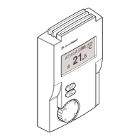
Assembly and Installation MATRIX control panel
22 PR-2011-0110-GB • Subject to modifications • R9-03-2016
5.4 Mounting MATRIX OP50x/51x control panels
For connecting the OP50/51 MATRIX control panel only the following cross sec-
tions may be used.
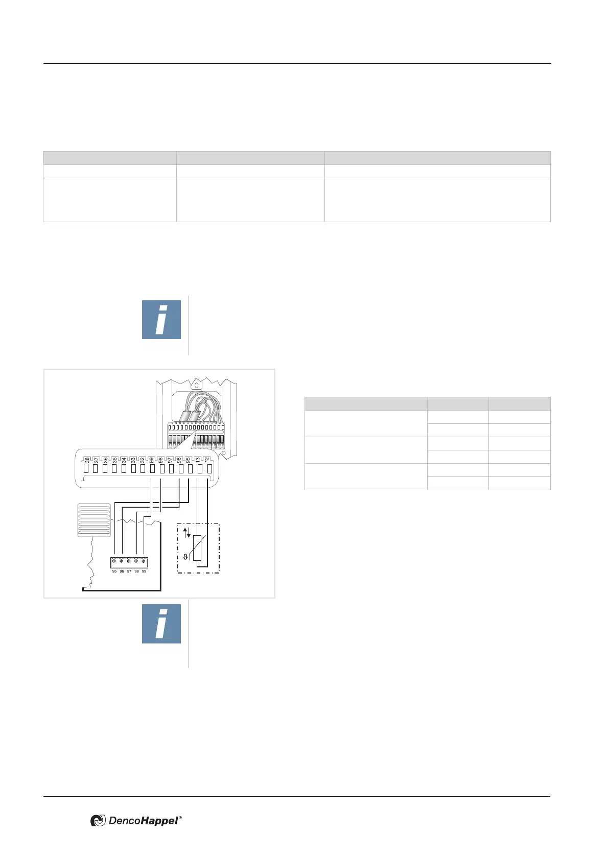
The following steps are required to connect the MATRIX control panel
– Connect mains electrical supply
– Connect MATRIX.Net
– Connecting external room temperature sensors (only for IP54 versions)
• Remove insulation from the wires and fasten each wire
according to the wiring diagram:
* imperative for IP54 versions;
alternatively it is possible to connect a room sensor
to the printed circuit board of the unit.
• Hook the front panel over the top of mounting plate. Ap-
ply light pressure to the bottom of the front panel until it
snaps into place.
Conductor type Number of conductors per terminal cross-sections min to max
Rigid conductor cross-section 1 0.22 to 0.5 mm
2
Flexible conductor cross-section 1 0.22 to 0.5 mm
2
0.22 to 0.5 mm
2
tinned
0.22 mm with wire end sleeve (4-side crimping tools, e.g.
Knipex pliers/tongs 975304)
NOTE!
For setting up MATRIX.net, only use data transfer cables that comply with DIN
19245 T3 and EN 50170, with twisted-pair wire and braided shield. - refer to
Chapter 5.5 "Cable recommendations MATRIX.Net" on page 23.
Klemme Signal
Room temperature sensor*
13
12
Supply voltage
95 GND
99 Vcc
MATRIX.Net
96 Low
98 High
NOTE!
If necessary, it is also possible to connect a room temperature sensor to IP20
models . With controllers of type MATRIX 3000/4000 a room temperature sen-
sor can be directly connected to the controller circuit board. (Refer to the oper-
ation manual of the relevant unit.)
 Loading...