31
31
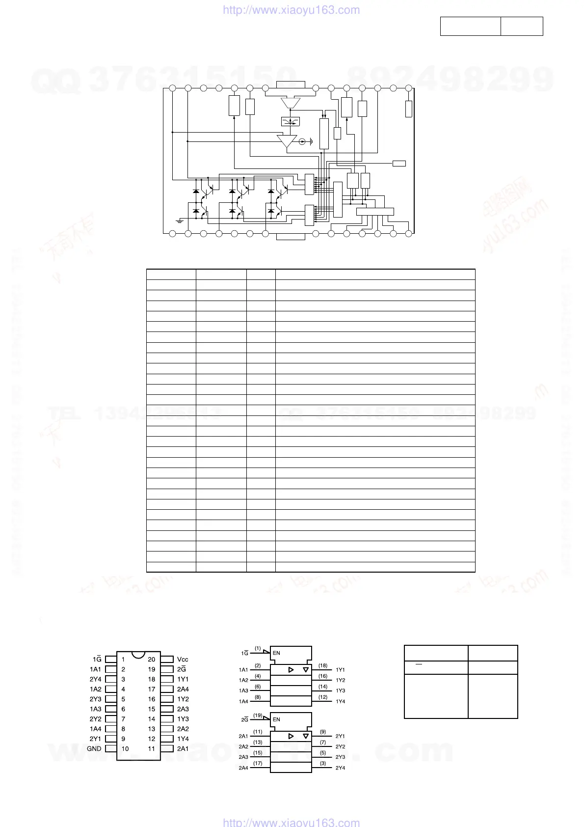
ADV-M71
FAN8423D3TF (ME: U7)
28 27 26 25 24 23 22 21 20 19 18 17 16 15
1234567
8
91011121314
NC
A3
NC
A2
NC
A1
GND
NC
H1+
H1-
H2+
H2-
H3+
H3-
CS1
VM
NC
VCC
FG1X
EC
ECR
S/S
DIR
FG3X
SB
PC1
NC
VH
FG1X
Generator
Start
Stop
-
+
Reverse Rota-
tion
Logic
Short
Brake
Hall
Commutation
Selector
Detec-
tor
Direc-
tion
Upper
Distribu-
Lower
Distribu-
Hall Amp
TSD
Current Sense
Amp
Output
Current Limit
Absolute
Values
FG3X
Generator
GND
GND
Pin Definitions
Pine Number Pin Name I/O Pin Function Description
1 NC - No connection
2 A3 O Output (A3)
3 NC - No connection
4 A2 O Output (A2)
5 NC - No connection
6 NC - No connection
7 A1 O Output (A1)
8 GND - Ground
9 H1+ I Hall signal (H1+)
10 H1- I Hall signal (H1-)
11 H2+ I Hall signal (H2+)
12 H2- I Hall signal (H2-)
13 H3+ I Hall signal (H3+)
14 H3- I Hall signal (H3-)
15 VH I Hall bias
16 NC - No connection
17 PC1 - Phase compensation capacitor
18 SB I Short brake
19 FG3X O FG waveform (3X)
20 DIR O Rotational direction output
21 ECR I Output current control reference
22 EC I Output current control voltage
23 S/S I Power save (Start/Stop switch)
24 FG1X O FG waveform (1X)
25 VCC - Supply voltage (Signal)
26 NC - No connection
27 VM - Supply voltage (Motor)
28 CS1 - Output current detection
logic symbol Function Table
INPUTS OUTPUT
GA Y
LH H
LL L
HX Z
SN74HCT244APW (MA: IC304)
SN74LV244APW (MA: IC708)
w
w
w
.
x
i
a
o
y
u
1
6
3
.
c
o
m
Q
Q
3
7
6
3
1
5
1
5
0
9
9
2
8
9
4
2
9
8
T
E
L
1
3
9
4
2
2
9
6
5
1
3
9
9
2
8
9
4
2
9
8
0
5
1
5
1
3
6
7
3
Q
Q
TEL 13942296513 QQ 376315150 892498299
TEL 13942296513 QQ 376315150 892498299
http://www.xiaoyu163.com
http://www.xiaoyu163.com
 Loading...