


N
Nicholas MurphyJul 25, 2025
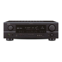
Why is my Denon Stereo Receiver display lit but no sound is produced?
- AAmber SullivanJul 26, 2025
There are several possible reasons: * The speaker cables might not be securely connected, so ensure they are. * The INPUT SELECTOR knob could be improperly set; adjust it to a suitable position. * The volume control might be set to minimum; increase the volume to a suitable level. * MUTING may be activated; switch it off. * If you've selected digital input, ensure digital signals are being input, or select the correct input terminals.