EasyManuals Logo

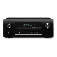
Denon AVR-2113CI Service Manual

Denon AVR-2113CI
222 pages
To Next Page IconTo Next Page
To Previous Page IconTo Previous Page
Page #171 background imageLoading...
Page #171 background image
171
W9864G6JH-6 Block diagram
W9864G2IH
Publication Release Date: Aug. 28, 2009
- 6 - Revision A03
6. BLOCK DIAGRAM
DQ0
DQ31
DQM0~3
CLK
CKE
A10
CLOCK
BUFFER
COMMAND
DECODER
ADDRESS
BUFFER
REFRESH
COUNTER
COLUMN
COUNTER
CONTROL
SIGN AL
GENERATOR
MODE
REGISTER
COLUMN DECODER
SENSE AMPLIFIER
CELL ARRAY
BANK #2
COLUMN DECODER
SENSE AMPLIFIER
CELL ARRAY
BANK #0
COLUMN DECODER
SENSE AMPLIFIER
CELL ARRAY
BANK #3
DATA CONTROL
CIRCUIT
DQ
BUFFER
COLUMN DECODER
SENSE AMPLIFIER
CELL ARRAY
BANK #1
NOTE:
The cell array configuration is 2048 * 256 * 32
ROW DECODER
ROW DECODER
ROW DECODERROW DECODER
A0
A9
BS0
BS1
CS
RAS
CAS
WE

Table of Contents

Other manuals for Denon AVR-2113CI

Questions and Answers:

Question and Answer IconNeed help?

Do you have a question about the Denon AVR-2113CI and is the answer not in the manual?

Denon AVR-2113CI Specifications

General IconGeneral
BrandDenon
ModelAVR-2113CI
CategoryReceiver
LanguageEnglish

Related product manuals