EasyManua.ls Logo

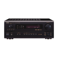
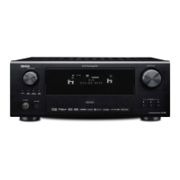
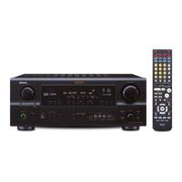
Denon AVR-2803

Denon AVR-2803
113 pages
To Next Page IconTo Next Page
Loading...
SERVICE MANUAL
MODEL
AVR‑2803/983
AVC‑2870
AV SURROUND RECEIVER/AMPLIFIER
For U.S.A., Canada, Europe, Asia,
China, Hong Kong, Taiwan R.O.C.,
Korea & Japan model
Some illustrations using in this service manual are
slightly different from the actual set.
Please use this service manual with referring to the
補修用性能部品の保有期間は、製造打切後8年です。
本機の仕様は性能改良のため、予告なく変更する
ことがあります。
本文中に使用しているイラストは、説明の都合上
現物と多少異なる場合があります。
修理の際は、必ず取扱説明書を参照の上、作業を
行ってください。
operating instructions without fail.
16-11, YUSHIMA 3-CHOME, BUNKYOU-KU, TOKYO 113-0034 JAPAN
Telephone: 03 (3837) 5321
X0163 V.01 DE/CDM 0302
Ver. 1
Table of Contents

Other manuals for Denon AVR-2803

Questions and Answers:

Denon AVR-2803 Specifications

General IconGeneral
Power Output90 W per channel (8 ohms, 20 Hz - 20 kHz, 0.05% THD)
Channels7.1
Dolby SupportDolby Digital, Dolby Pro Logic II
Digital Inputs2 coaxial, 3 optical
Weight14.5 kg
TypeAV Receiver
Output Power per Channel90 W (8 ohms, 20 Hz - 20 kHz, 0.05% THD)
Frequency Response10 Hz - 100 kHz (+1, -3 dB)
Input Sensitivity200 mV
Input Impedance47 kOhms
Total Harmonic Distortion0.05%
Input Sensitivity/Impedance200 mV / 47 kOhms
Tuner Frequency RangeFM: 87.5 - 108 MHz, AM: 522 - 1611 kHz
DTS SupportDTS, DTS-ES, DTS Neo:6
OutputsComposite: 2, Component: 1
Video outputsComposite: 2

Summary

Safety Precautions

Leakage Current Check

Check for customer safety before returning the unit, ensuring proper electrical insulation.

Disassembly Procedures

PowerControl Unit Check

Method for checking the power and control unit while the unit is powered on.

Servicing Cautions and Initialization

AV Receiver Initialization

Procedure to initialize the AV SURROUND RECEIVER, typically after component replacement.

Adjustment Procedures

Audio Section Idling Current Adjustment

Procedure for adjusting the idling current in the audio section.

System Diagrams

Wiring Diagram

Overall wiring diagram showing connections between different units and components.

Schematic Diagrams (Parts 1-12)

Detailed schematic diagrams for various receiver units, presented in 12 parts.

Schematic Diagrams (Japan Models)

Detailed schematic diagrams for units specific to Japan models.

Test Mode Operations

comDSP Error Display Mode

Procedure to check for and display microcomputer or DSP errors using a specific test mode.

Printed Wiring Board Layouts

Parts List Conventions

Parts List Notation

Explains symbols and notation used in the parts list for resistors, capacitors, and units.

Parts List by Unit (Except Japan)

1 U-3469 Power Unit Parts

List of semiconductor and resistor parts for the 1U-3469 POWER UNIT (Except Japan model).

Parts List by Unit (For Japan)

Exploded View and Parts List

Exploded View of Components

Visual representation of the unit's components and their assembly order.

Exploded View Parts List

Detailed list of all parts referenced in the exploded view, categorized by unit.

Related product manuals