EasyManua.ls Logo

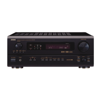
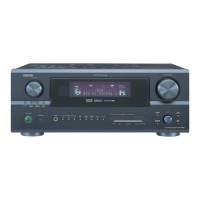
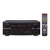
Denon AVR-2801/981

Denon AVR-2801/981
127 pages
To Next Page IconTo Next Page
Loading...
Hi-Fi Component
SERVICE MANUAL
MODEL
AVR-2801/981
AV SURROUND RECEIVER
Some illustrations using in this service manual are slightly different from the actual set.
TUNING
BAND
TITLE
MENU/GUIDE
MODE
MEMORY
USE/LEARN T.TONE MULTI OUTPUT SET UP
RETURN
STATUS
DISPLAY
ON SCREEN
SYSTEM
SETUP
SURROUND
PARAMETER
CH SELECT
SELECT
ENTER
w
w
w
.
x
i
a
o
y
u
1
6
3
.
c
o
m
Q
Q
3
7
6
3
1
5
1
5
0
9
9
2
8
9
4
2
9
8
T
E
L
1
3
9
4
2
2
9
6
5
1
3
9
9
2
8
9
4
2
9
8
0
5
1
5
1
3
6
7
3
Q
Q
TEL 13942296513 QQ 376315150 892498299
http://www.xiaoyu163.com

Table of Contents

Question and Answer IconNeed help?

Do you have a question about the Denon AVR-2801/981 and is the answer not in the manual?

Denon AVR-2801/981 Specifications

General IconGeneral
ModelAVR-2801/981
Channels5.1
Power Output (RMS)90W per channel (8 ohms, 20Hz-20kHz, 0.05% THD)
Total Harmonic Distortion (THD)0.05%
Frequency Response10Hz - 100kHz (+1, -3dB)
Input Sensitivity200mV (line)
Weight14.5 kg
Video ConnectionsComposite, S-Video
Input Impedance47 kOhms
Dimensions (W x H x D)434 x 171 x 429 mm
Tuning rangeFM/AM
Speaker load impedance6Ω to 16Ω
Digital inputscoaxial, optical

Summary

Safety Precautions and Specifications

Safety Precautions

Important safety guidelines for service technicians and user protection.

Unit Specifications

Detailed technical specifications for audio, video, tuner, and general features.

Audio Section Specifications

Performance characteristics of the power amplifier, dynamic power, and output terminals.

Video Section Specifications

Technical details for standard and S-video input/output levels and frequency response.

Disassembly Procedures

Unit Component Removal

Power Amp -com Unit Check

Steps to check the power amp and µ-com unit with power-on.

Signal Level Diagrams

Adjustment Procedures

Tuner Section Alignment

Procedures for aligning FM/MPX and AM tuner sections.

Audio Section Idling Current Adjustment

Printed Wiring Board Layouts

AudioDSP P.W.B. Diagrams

Component and foil side layouts for the Audio/DSP Printed Wiring Board.

Extension Input P.W.B. Diagrams

Component and foil side layouts for the Extension Input Printed Wiring Board.

Control P.W.B. Diagrams

Component and foil side layouts for the Control Printed Wiring Board.

Power & Regulator P.W.B. Diagrams

Component and foil side layouts for Power and Regulator PWBs.

Parts List - 1 U-3323 AUDIODSP UNIT ASSY

Parts List - 1 U-3323 EXT. UNIT ASSY

Parts List - 1 U-3321 CONTROL UNIT ASSY

Parts List - 1 U-3235 REGULATOR UNIT ASSY

Semiconductors Group

List of semiconductors used in the 1U-3235 REGULATOR UNIT ASS'Y.

Resistors Group

List of resistors used in the 1U-3235 REGULATOR UNIT ASS'Y.

Parts List of Exploded View

Exploded View Assembly

Block Diagram

Schematic Diagrams (113)

Schematic Diagrams (213)

Schematic Diagrams (313)

Schematic Diagrams (413)

Schematic Diagrams (513)

Schematic Diagrams (613)

Schematic Diagrams (713)

Schematic Diagrams (1013)

Schematic Diagrams (813)

Schematic Diagrams (913)

Schematic Diagrams (1313)

Schematic Diagrams (1113)

Schematic Diagrams (1213)

Related product manuals