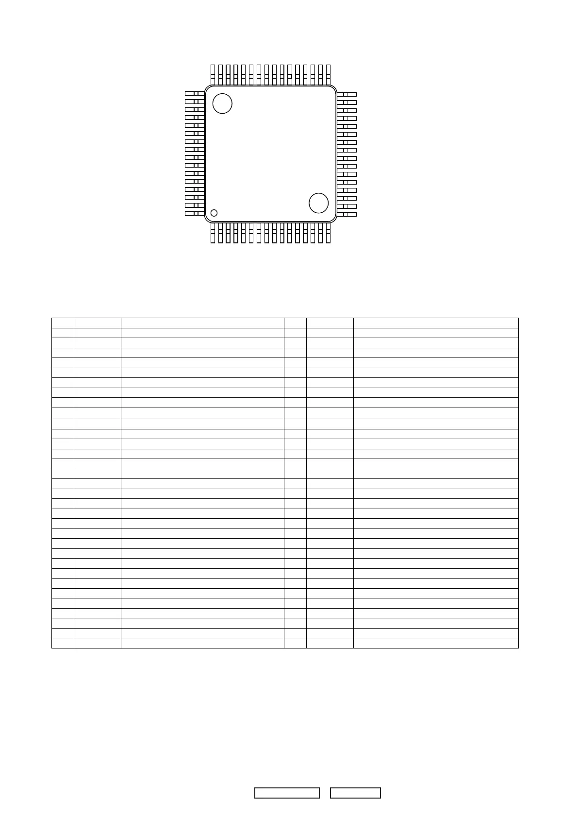
NJW1153
– 2 –
�
��
� PIN FUNCTION
No. SYMBOL FUNCTION No. SYMBOL FUNCTION
1 FIL2_R
Rch Bass filter terminal
33 RAIN
Multi-channel Rch input A
2 FIL3_R
Rch Bass filter DC cut capacitor output terminal
34 CAIN
Multi-channel Cch input A
3 FIL4_R
Rch Bass filter DC cut capacitor input terminal
35 SLAIN
Multi-channel SLch input A
4 GND
Ground
36 SRAIN
Multi-channel SRch input A
5 FL+
“Input selector gain control” Lch no-inverted output
37 SWAIN
Multi-channel SWch input A
6 FL-
“Input selector gain control” Lch inverted output
38 LBIN
Multi-channel Lch input B
7 FR+
“Input selector gain control” Rch no-inverted output
39 RBIN
Multi-channel Rch input B
8 FR-
“Input selector gain control” Rch inverted output
40 CBIN
Multi-channel Cch input B
9 DCLA1
“Input selector” Lch output
41 SLBIN
Multi-channel SLch input B
10 DCLA2
“Multi-channel selector” Lch input
42 SRBIN
Multi-channel SRch input B
11 DCRA1
“Input selector” Rch output
43 SWBIN
Multi-channel SWch input B
12 DCRA2
“Multi-channel selector” Rch input
44 SurTC
Switching noise rejection capacitor
13 L1IN
“Input selector” Lch input 1
45 FIL4_L
Lch Bass filter DC cut capacitor input terminal
14 R1IN
“Input selector” Rch input 1
46 FIL3_L
Lch Bass filter DC cut capacitor output terminal
15 L2IN
“Input selector” Lch input 2
47 FIL2_L
Lch Bass filter terminal
16 R2IN
“Input selector” Rch input 2
48 FIL1_L
Lch Treble filter terminal
17 L3IN
“Input selector” Lch input 3
49 LOUT
Lch output
18 R3IN
“Input selector” Rch input 3
50 ROUT
Rch output
19 L4IN
“Input selector” Lch input 4
51 COUT
Cch output
20 R4IN
“Input selector” Rch input 4
52 SLOUT
SLch output
21 L5IN
“Input selector” Lch input 5
53 SROUT
SRch output
22 R5IN
“Input selector” Rch input 5
54 SWOUT
SWch output
23 L6IN
“Input selector” Lch input 6
55 V+
+ Power supply voltage input
24 R6IN
“Input selector” Rch input 6
56 GND
Ground
25 L7IN
“Input selector” Lch input 7
57 V-
- Power supply voltage input
26 R7IN
“Input selector” Rch input 7
58 RECL1
“Input selector” Lch REC output 1
27 L8IN
“Input selector” Lch input 8
59 RECR1
“Input selector” Rch REC output 1
28 R8IN
“Input selector” Rch input 8
60 RECL2
“Input selector” Lch REC output 2
29 DATA
Control data signal input
61 RECR2
“Input selector” Rch REC output 2
30 CLOCK
Clock signal input
62 RECL3
“Input selector” Lch REC output 3
31 LATCH
Latch signal input
63 RECR3
“Input selector” Rch REC output 3
32 LAIN
Multi-channel Lch input A
64 FIL1_R
Rch Treble filter terminal
1 16
17
32
48
49
64
33

 Loading...