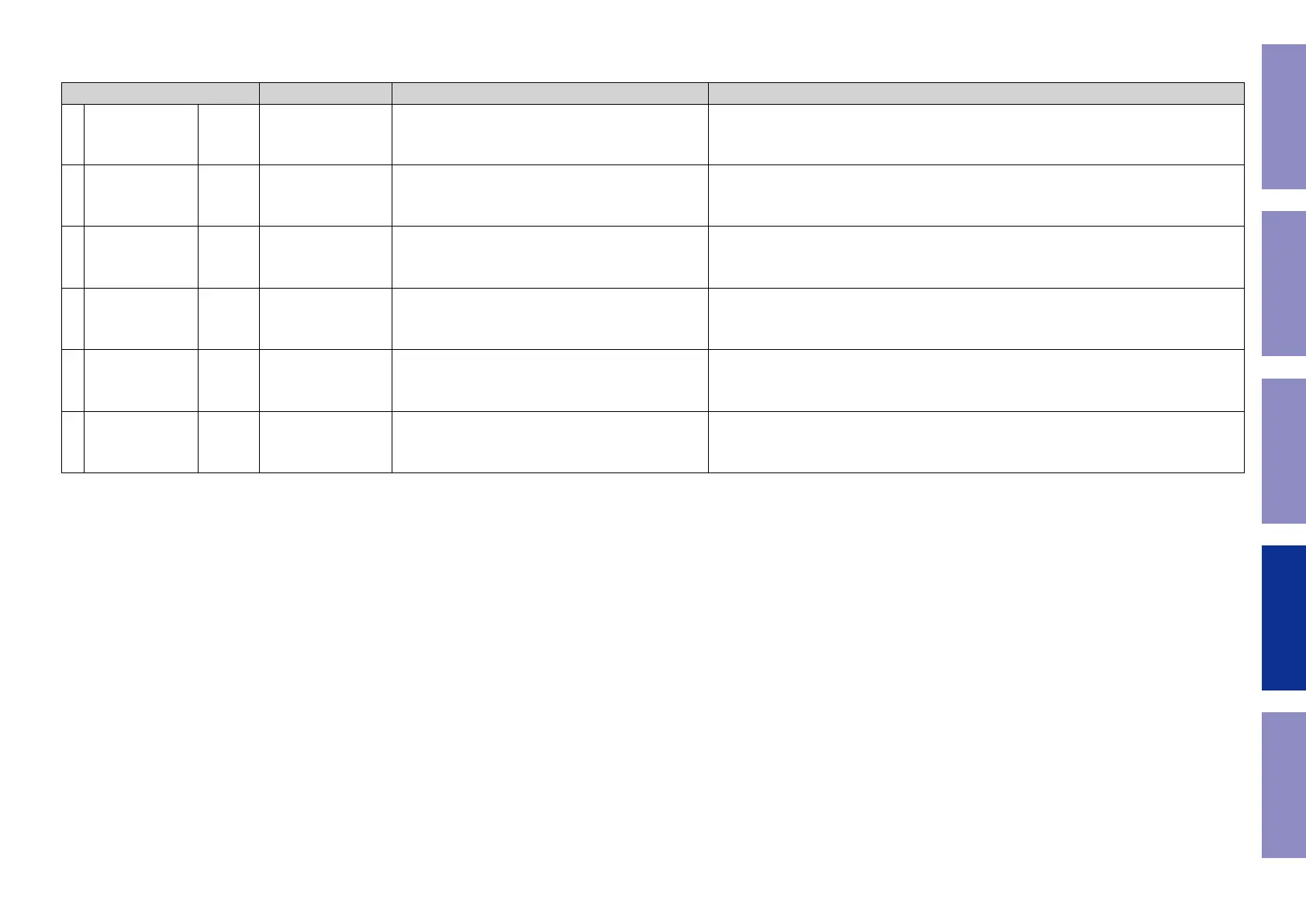
1.6. Conrmation items for the video system
See the block diagram g.VXXth.
Paths to be conrmed Display Settings What to conrm
1 Analog Video pass g.V01
V01:VIDEO PASS
Input Source : CBL/SAT • CVBS input ⇒ CVBS output
(
b
The input source can be switched to any source except CBL/SAT.)
2
HDMI pass
(MAIN ZONE)
g.V02
V03:HDMI PASS
Input Source : CBL/SAT
MAIN ZONE ON
• HDMI input ⇒ HDMI output (MAIN)
(
b
The input source can be switched to any source except CBL/SAT.)
3 HDMI CEC g.V03
V04:HDMI CEC
Input Source : CBL/SAT
HDMI Control : On
• When the power supply of a TV is put in the standby mode, make sure that the power supply
of this unit is also put in the standby mode.
(
b
The input source can be switched to any source except CBL/SAT.)
• The ARC path can also be checked (check this using the TV input source).
4
HDMI Audio
(Audio : AVR)
g.A03a
g.A03b
V05:H.AUDIO-AVR
Input Source : CBL/SAT
HDMI Control : Off
HDMI Audio : AVR (if checking the audio output from
AVR)
• HDMI input (PCM, DolbyDigital, DTS) ⇒ Speaker output.
• HDMI input(HD audio) ⇒ Speaker output.
(
b
The input source can be switched to any source except CBL/SAT.)
5
HDMI Audio
(Audio : TV)
g.V05
V06:H.AUDIO-TV
HDMI Audio : TV (if checking the audio output from TV) • HDMI input (PCM, DolbyDigital, DTS) ⇒ HDMI output (audio output from connected TV)
(
b
The input source can be switched to any source except CBL/SAT.)
6 GUI g.V06
V07:GUI MENU ON
Input Source : CBL/SAT
Setup Menu : On
• GUI display ⇒ HDMI output.
(
b
The input source can be switched to any source except CBL/SAT.)
Before Servicing
This Unit
Electrical Mechanical Repair Information Updating
119
 Loading...