Explanatory Photos for DISASSEMBLY
• Fortheshootingdirectionofeachphotosusedinthismanual,seethephotobelow.
• A, B, C and Dinthephotobelowindicatetheshootingdirectionsofphotos.
• Thephotographswithnoshootingdirectionindicatedweretakenfromthetopoftheunit.
•PhotosofAVR-S650HE3areusedinthismanual.
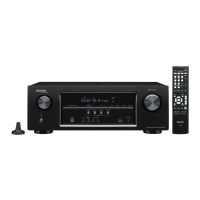
The viewpoint of each photograph
(Shootingdirection:X)[Viewfromthetop]
↓Shooting direction: C↓
↑Shooting direction: D↑
↑Shooting direction: A↑
↓Shooting direction: B↓
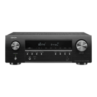
Proceeding : TOP COVER → FRONT PANEL ASSY
(1) Removethescrews.
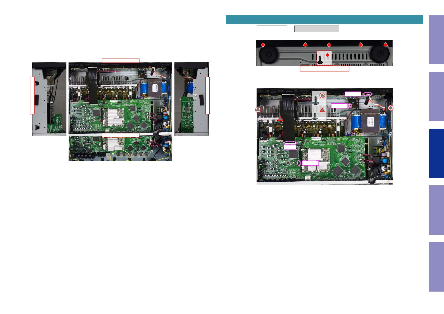
(2) Removethescrews.Removetheconnector.RemovetheFFC.
1. FRONT PANEL ASSY
View from the bottom
x5
x2
x1
CN102
CN104
FFC
CN813
Before Servicing
This Unit
Electrical Mechanical Repair Information Updating
60
 Loading...