Proceeding : TOP COVER → REAR PANEL → DIGITAL PCB → VIDEO PCB
→ INPUT PCB → TUNER PCB
See"EXPLODEDVIEW"forinstructionsonremovingtheTUNERPCB.
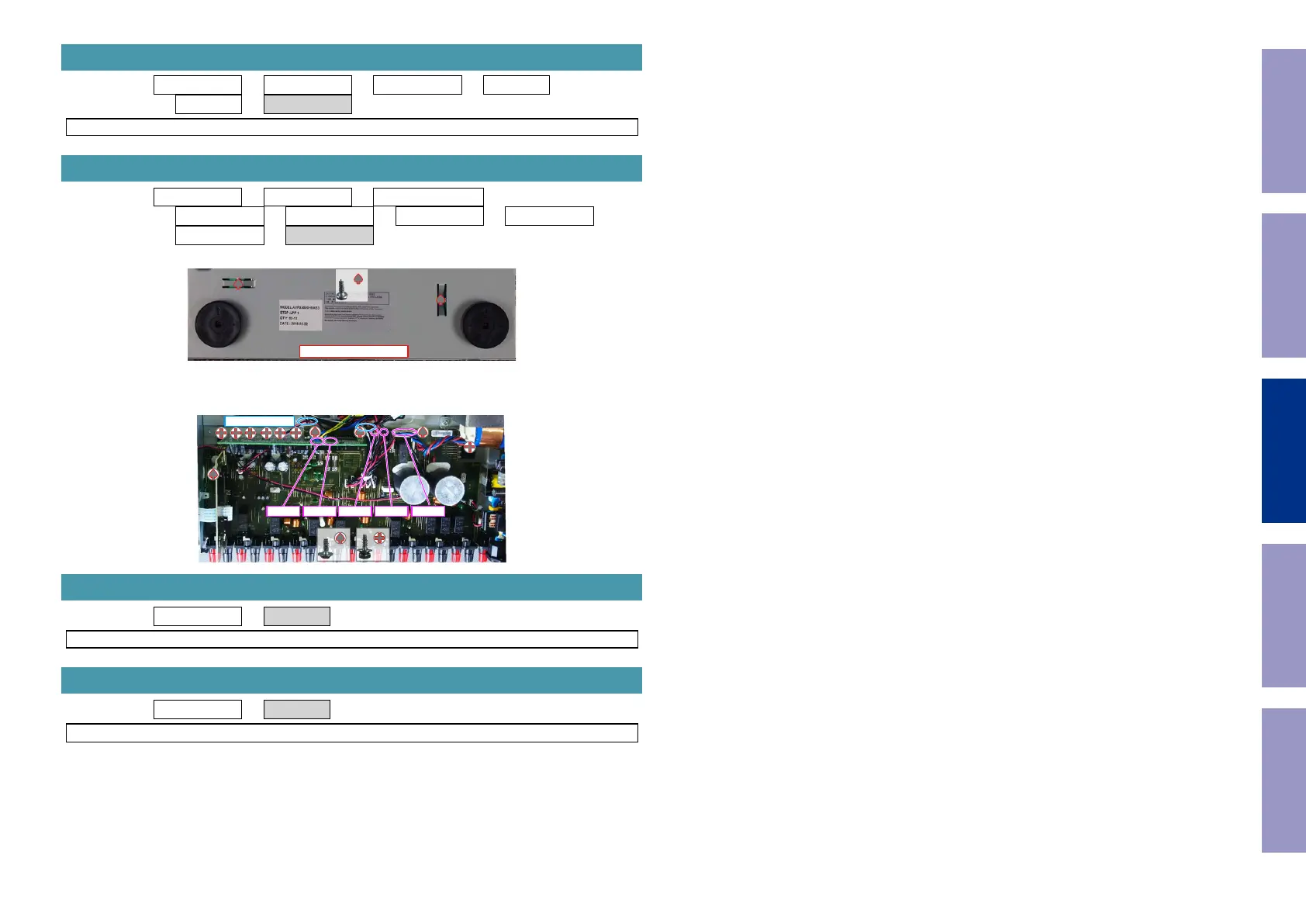
Proceeding : TOP COVER → FRONT ASSY → RADIATOR ASSY
→ REAR PANEL → DIGITAL PCB → VIDEO PCB → INPUT PCB
→ TUNER PCB → SPK PCB
(1) Removethescrews.
(2) Removethescrews.Removetheconnector.RemovetheSTYLEPIN.
Proceeding : TOP COVER → SMPS PCB
See"EXPLODEDVIEW"forinstructionsonremovingtheSMPSPCB.
Proceeding : TOP COVER → TRANS
See"EXPLODEDVIEW"forinstructionsonremovingthetransformer(TRANS).
7. TUNER PCB
8. SPK PCB
View from the bottom
x2
x4 x7
CN941 CN940 CN712 CN711 CN971
STYLE PIN x2
9. SMPS PCB
10. TRANS
Before Servicing
This Unit
Electrical Mechanical Repair Information Updating
85

 Loading...