ADV7623 Hardware Manual
Rev. 0 – March 2010 20 Confidential NDA required
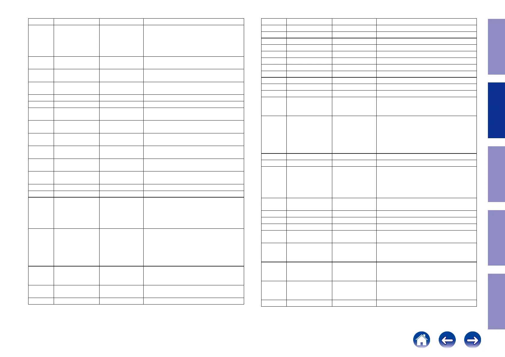
Location Mnemonic Type Description
68 MCLK_IN Digital Input Audio Reference Clock. 128 × N × fs with
N = 1, 2, 3, or 4. Set to 128 × sampling
frequency (fs), 256 × fs, 384 × fs, or 512 ×
fs. Supports 1.8 V to 3.3 V CMOS logic
levels.
69 SCLK_IN Digital Input I2S Audio Clock. Supports CMOS logic
levels from 1.8 V to 3.3 V.
70 AP5_IN Digital Input Audio Input Port 5. CMOS logic levels
from 1.8 V to 3.3 V.
71 AP4_IN Digital Input Audio Input Port 4. CMOS logic levels
from 1.8 V to 3.3 V.
72 DGNDIO Ground Ground for DVDDIO
73 DVDDIO Power Digital I/O supply voltage (3.3 V)
74 AP3_IN Digital Input Audio Input Port 3. CMOS logic levels
from 1.8 V to 3.3 V.
75 AP2_IN Digital Input Audio Input Port 2. CMOS logic levels
from 1.8 V to 3.3 V.
76 AP1_IN Digital Input Audio Input Port 1. CMOS logic levels
from 1.8 V to 3.3 V.
77 AP0_IN Digital Input Audio Input Port 0. CMOS logic levels
from 1.8 V to 3.3 V.
78 SDATA Digital I/O I2C port serial data input/output pin. SDA
is the data line for the control port.
79 SCL Digital Input I2C port serial clock input. SCL is the clock
line for the control port.
80 DGND Ground Ground for DVDD
81 DVDD Power Digital supply voltage (1.8 V)
82 INT1
(AMUTE1)
Digital Output Interrupt pin, can be active low or active
high. When status bits change, this pin is
triggered. The events that trigger an
interrupt are under user control. This pin
can also output an audio mute signal
83 INT2
(AMUTE2)
Digital Output Interrupt pin, can be active low or active
high. When status bits change, this pin is
triggered. The events that trigger an
interrupt are under user control. This pin
can also output an audio mute signal.
I2C LSB selection.
84 INT_TX Digital Output Interrupt. Open drain. A 2 kΩ pull-up
resistor to the microcontroller I/O supply is
recommended.
85 DGNDIO
Ground
Ground for DVDDIO
86 DVDDIO Power Digital I/O supply voltage (3.3 V)
ADV7623 Hardware Manual
Rev. 0 – March 2010 21 Confidential NDA required
Location Mnemonic Type Description
87 AP0_OUT Digital Output Audio output port 0.
88 AP1_OUT Digital Output Audio output port 1.
89 AP2_OUT Digital Output Audio output port 2.
90 AP3_OUT Digital Output Audio output port 3.
91 AP4_OUT Digital Output Audio output port 4.
92 DGND Ground Ground for DVDD
93 DVDD Power Digital supply voltage (1.8 V)
94 AP5_OUT Digital Output Audio output port 5.
95 SCLK_OUT Digital Output Audio serial clock output.
96 MCLK_OUT Digital Output Audio master clock output.
97 RESETB Digital Input System reset input. Active low. A minimum
low reset pulse width of 5 ms is required to
reset the ADV7623 circuitry.
98 PWRDNB Digital Input Active low power-down pin. This pin
should be used as a system power detect
when the internal EDID is powered from
the 5V signal from the HDMI port when
connected to active equipment. Pin pulled
down internally.
99 PGND Ground Ground for PVDD
100 PVDD Power PLL supply voltage
101 XTAL Miscellaneous
Analog
Input pin for 28.63636 MHz crystal or an
external 1.8 V 28.63636 MHz clock
oscillator source to clock the ADV7623.
The following crystal frequencies are also
supported: 24.576 MHz and 27 MHz.
102 XTAL1 Miscellaneous
Analog
Crystal output pin. This pin should be left
floating if a clock oscillator is used.
103 PVDD Power PLL supply voltage
104 PGND Ground PVDD Ground
105 HP_CTRLA Digital Output Hot Plug Detect for port A.
106 5V_DETA Digital Input 5 V detect pin for port A in the HDMI
interface.
107 RTERM Miscellaneous
Analog
Sets internal termination resistance. A 500
Ω resistor between this pin and GND
should be used.
108 DDCA_SDA Digital I/O HDCP slave serial data port A.
DDCD_SDA is a 3.3 V input/output that is
5 V tolerant.
109 DDCA_SCL Digital Input HDCP slave serial clock port A.
DDCD_SCL is a 3.3 V input that is 5 V
tolerant.
110 CVDD Power Receiver comparator supply voltage (1.8V)
36
Caution in
servicing
Electrical Mechanical Repair Information Updating

 Loading...