8
ENGLISH
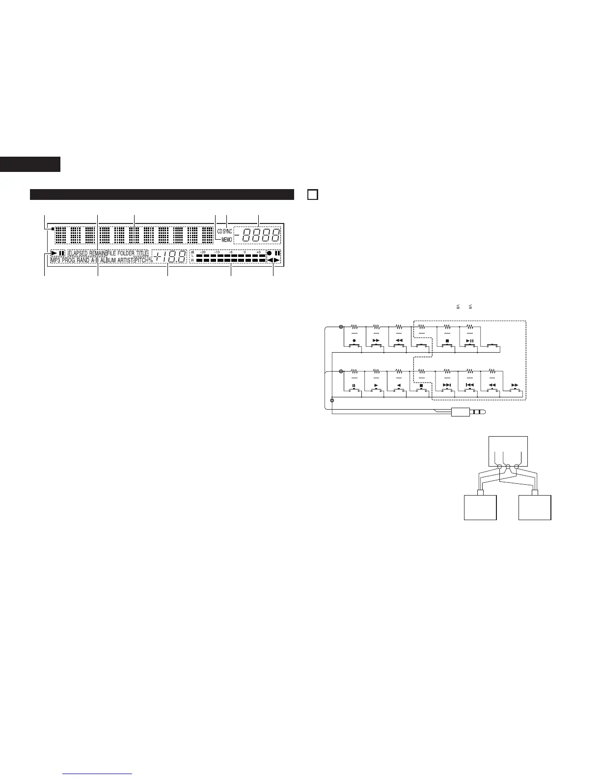
q
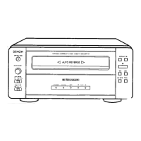
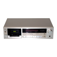
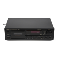
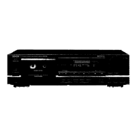
CD transport indicator
w
Mode display portion (CD)
• Indicator for MP3 is DN-T645 only.
FILE : This lights when the file name of MP3
is displayed.
FOLDER: This lights in the folder selection mode.
TITLE : This lights when the title in the MP3
ID3-Tag or CD Text is displayed.
MP3 : This lights when a disc containing MP3
format file is loaded.
PROG : This lights in the program mode.
RAND : This lights in the random mode.
A-B : This lights in the A-B repeat playback
mode.
ALBUM : This lights when the album name in the
MP3 ID3-Tag is displayed.
ARTIST : This lights when the artist name in the
MP3 ID3-Tag is displayed.
e
CD pitch display
r
Level meter
t
Cassette deck transport indicator
y
Tape counter
u
CD synchronized recording indicator
• This lights in the CD synchronized recording
mode.
i
Memory stop indicator
o
Multiple display
• This displays Track No. of CD, playing time of
CD, various operational information, text
message, etc.
!0
Time mode indicator
ELAPSED: This lights when the elapsed time is
displayed.
REMAIN : This lights when the remaining time is
displayed.
!1
Infrared remote control indicator
(3) Display
3
CONNECTIONS
Leave your entire system (including the DN-T645/625) turned off until all connections between the DN-T645/625
and other components have been completed.
2 Connection precautions
• Before proceeding with connections or disconnections of cables and power cords, be sure to turn all
system components off.
• Ensure that all cables are connected properly to the L (left) and R (right) jacks.
• Insert plugs fully into the terminals.
• Connect the CD output jacks to the amplifier CD or AUX input jacks.
ø3.5mm
STEREO MINI PLUG
• Up to six units can be controlled simultaneously
with one remote control unit.
• Wire the signal and ground lines as shown on the
diagram below and connect at the remote control
inputs (C1, C2 and C3).
• Design the circuit so that the resistance of the
individual wires is 0.5 Ω/ohms or less.
Connecting two DN-T645/625 units (N = 2)
Remote Unit
2 Remote control connections
(1) RC IN
• For wired remote control, use the circuit shown on the diagram below.
• Design the circuit so that the wire resistance is 0.5 Ω/ohms or less.
✽ 1 N 6
(“N” is the number of DN-T645/625 units connected.)