o
Parallel remote control port
(PARALLEL) (DN-T645 only)
• This is a parallel remote connector.
• Applicable connector : 25-pin D-sub (male)
• Connecting signal layout : See page 9.
!0
BALANCED OUT (CD) connectors
• These are active balanced outputs using XLR
type connections. The CD’s playback signals
are output from these connectors.
• Pin layout : 1. Common / 2. Hot / 3. Cold
• Applicable connector :
Cannon XLR-3-31 or equivalent.
7
ENGLISH
#9
Number buttons
(1, 2, 3, 4, 5, 6, 7, 8, 9 and 0/CLEAR)
• Use these buttons for the direct search and
program memory functions.
• For direct search, press for example button
if you want to hear track number 3.
For track number 12, press then .
To program tracks, press the PROGRAM/DIRECT
button $0 to set to the program mode.
$0
PROGRAM/DIRECT button
• Press this button when you want to enter
tracks for programmed playback. (Refer to
page 11 for details.)
• When the button is pressed, the “PROG”
indicator is lit.
$1
REPEAT switch
• When set to the “ON” side, repeat play mode
is set.
• The selected track is played repeatedly when in
the single play mode, and all the tracks on the
disc are played repeatedly when in the
continuous play mode.
• The REPEAT switch functions in the normal
play, program play, and random play modes.
• When set back to the “OFF” side, the normal
play mode is set.
$2
PLAY MODE switch
• Use this to select the play mode.
• The PLAY MODE switch functions in the
normal play, program play, random play and A-
B repeat play modes.
SINGLE : (single track play mode)
The stop mode is set after the specified track
is played.
CONT. : (continuous play mode)
The stop mode is set after the last track is
played.
q
UNBALANCED IN jacks
• These are unbalanced inputs using RCA type
jacks.
Use them to input signals to be recorded on a
tape.
w
UNBALANCED OUT (TAPE/MIX) jacks
• These are unbalanced outputs using RCA type
jacks.
The tape’s playback signals or the mixed tape
and CD playback signals are output from these
jacks.
e
UNBALANCED OUT (CD) jacks
• These are unbalanced outputs using RCA type
jacks.
The CD’s playback signals are output from
these jacks.
r
DIGITAL OUT (CD) jack
• This is an coaxial output using an RCA type
jack.
• Signal format : SPDIF or IEC-958 Type
II
t
External synchronized control jacks
(EXT. SYNC.)
• Connect these for synchronized recording.
y
Cascade control jacks (CASCADE)
• Connect these for continuous operation on
multiple units.
• When the RELAY MODE switch !3 is set to
“CASCADE”, the start signal is output from
this output jack once operation of Deck side is
finished.
u
RC IN control jack
• This is a stereo mini jack for wired remote
control.
(2) Rear panel
NOTE :
• Do not short-circuit the hot or cold pin with
the common pin.
!1
MONO OUT ON/OFF switch
• Select the signal from the balanced outputs of
CD and cassette deck.
OFF : Stereo signal output (Normal)
ON : L/R mixed monaural signal output with
different levels
✽ LOW level (
_
10 dBu) of R channel could be
convenient when you need to feed the output
of DN-T645/625 into a Mic level input terminal
on mixer console etc. in order to avoid overload
by normal Line level input.
!2
BALANCED OUT (TAPE/MIX)
connectors
• These are active balanced outputs using XLR
type connectors. The tape’s playback signals or
the mixed tape and CD playback signals are
output from these connectors.
• Pin layout : 1. Common / 2. Hot / 3. Cold
• Applicable connector :
Cannon XLR-3-31 or equivalent
!3
BALANCED IN connectors
• These are active balanced inputs using XLR
type connectors. Use these connectors to
input signals to be recorded on a tape.
• Pin layout : 1. Common / 2. Hot / 3. Cold
• Applicable connector :
Cannon XLR-3-32 or equivalent
!4
INPUT SELECT switch
• Use this select the recording input signals
(BALANCED or UNBALANCED).
NOTE :
• Do not short-circuit the hot or cold pin with
the common pin.
i
Serial control port
(DN-T645 : RS232C/RS422A,
DN-T625 : RS232C)
• This is serial remote connector.
• Applicable connector : 9-pin D-sub (male)
• Baud rate : 9600 bps
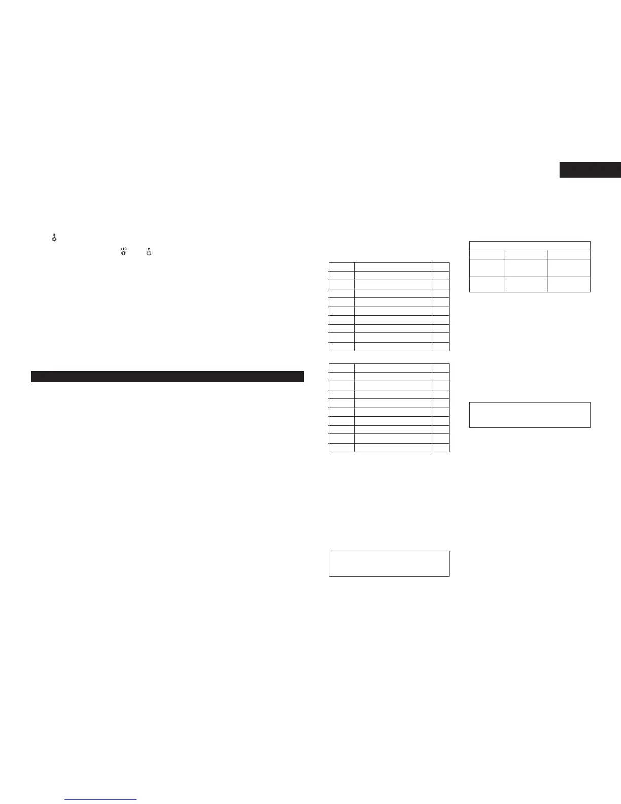
• Pin layout
Pin No.
Signal Name
1
6NC
GND
I / O
_
_
2
7NC
TxD O
_
3
8NC
RxD I
_
4
9NC
NC
_
_
5 S. GROUND
_
RS-232C
Pin No.
Signal Name
1
6 S. GROUND
GND
I / O
_
_
2
7 TxD
TxD (RETURN) O
O
3
8 RxD (RETURN)
RxD I
I
4
9NC
NC
_
_
5NC
_
RS-422A (DN-T645 only)
L channel :
HIGH
Monaural Output Signal Level
CD
+18 dBu
(Normal level)
Cassette deck
+4 dBu
(Normal level)
R channel :
LOW
_
10 dBu
_
10 dBu