36
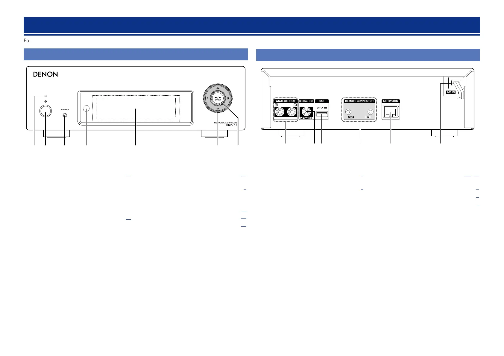
Part names and functions
For buttons not explained here, see the page indicated in parentheses ( ).
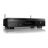
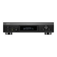
Front panel
w re t y u
q
q Power indicator ·········································· (20)
The power indicator changes as shown below
according to the status of the unit.
•Power on : Green
•Standby : Off
•Network Control – “On” : Red
•iPod charge standby : Red
w Power operation button (X) ······················ (20)
Turns power to this unit on and off (standby).
e Input source select button (SOURCE) ······ (20)
Selects the input source.
r Remote control sensor ································ (3)
t Display
Displays play status, settings, etc.
y Cursor button (uio p) ···························· (20)
u Play/Pause button (1/3) ·························· (20)
ENTER button ············································· (20)
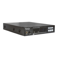
q ANALOG OUT connectors ··························· (6)
Connect a commercially available amp.
w DIGITAL OUT connector ······························ (6)
Connect a digital device such as a commercially
available AV receiver or D/A converter.
Rear panel
wq e tr y
e USB port ················································ (26, 28)
Used to connect iPod or USB memory devices.
r REMOTE CONNECTOR jacks ······················· (7)
t ETHERNET connector ·································· (8)
y AC cord (AC IN) ············································· (9)
 Loading...