EasyManua.ls Logo

Denon DR-M33HX - Control Circuit Board Removal; FL Meter Removal; CTS Circuit Board Removal (DR-M44 HX only); Audio Circuit Board Removal

Denon DR-M33HX
48 pages
Print Icon
To Next Page IconTo Next Page
To Previous Page IconTo Previous Page
Loading...
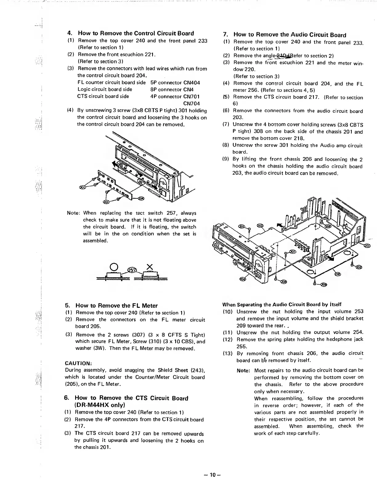
4.
H
ow
to
Remove
the
Control
Circuit
Board
(1)
Remove
the
top
cover
240
and
the
front
panel
233
(Refer
to
section
1)
(2)
Remove
the
front
escuchion
221.
(Refer
to
section
3)
(3)
Remove
the
connectors
with
lead
wires
which
run
from
the
control
circuit
board
204.
FL
counter
circuit
board
side
5P
connector
CN404
Logic
circuit
board
side
8P
connector
CN4
CTS
circuit
board
side
4P
connector
CN701
CN704
(4)
By
unscrewing
3
screw
(3x8
CBTS
P
tight)
301
holding
the
control
circuit
board
and
loosening
the
3
hooks
on
the
control
circuit
board
204
can
be
removed.
Note;
When
replacing
the
tact
switch
257,
always
check
to
make
sure
that
it
is
not
floating
above
the
circuit
board.
If
it
is
floating,
the
switch
will
be
in
the
on
condition
when
the
set
is
assembled.
7.
How
to
Remove
the
Audio
Circuit
Board
(1)
Remove
the
top
cover
240
and
the
front
panel
233.
(Refer
to
section
1)
(2)
Remove
the
angl
e
?
1P
^"f''r
to
section
2)
(3)
Remove
the
front
escuchion
221
and
the
meter
win¬
dow
220.
(Refer
to
section
3)
(4)
Remove
the
control
circuit
board
204,
and
the
FL
meter
256.
(Refer
to
sections
4,
5)
(5)
Remove
the
CTS
circuit
board
217.
(Refer
to
section
6
)
(6)
Remove
the
connectors
from
the
audio
circuit
board
203.
(7)
Unscrew
the
4
bottom
cover
holding
screws
(3x8
CBTS
P
tight)
308
on
the
back
side
of
the
chassis
201
and
remove
the
bottom
cover
218.
(8)
Unscrew
the
screw
301
holding
the
Audio
amp
circuit
board.
(9)
By
lifting
the
front
chassis
206
and
loosening
the
2
hooks
on
the
chassis
holding
the
audio
circuit
board
203,
the
audio
circuit
board
can
be
removed.
5.
How
to
Remove
the
FL
Meter
(1)
Remove
the
top
cover
240
(Refer
to
section
1)
(2)
Remove
the
connectors
on
the
FL
meter
circuit
board
205.
(3)
Remove
the
2
screws
(307)
(3
x
8
CFTS
S
Tight)
which
secure
FL
Meter,
Screw
(310)
(3
x
10
CBS),
and
washer
(3W).
Then
the
FL
Meter
may
be
removed.
CAUTION:
During
assembly,
avoid
snagging
the
Shield
Sheet
(243),
which
is
located
under
the
Counter/Meter
Circuit
board
(205),
on
the
FL
Meter.
6.
How
to
Remove
the
CTS
Circuit
Board
(DR-M44HX
only)
(1)
Ftemove
the
top
cover
240
(Refer
to
section
1)
(2)
Remove
the
4P
connectors
from
the
CTS
circuit
board
217.
(3)
The
CTS
circuit
board
217
can
be
removed
upwards
by
pulling
it
upwards
and
loosening
the
2
hooks
on
the
chassis
201.
When
Separating
the
Audio
Circuit
Board
by
itself
(10)
Unscrew
the
nut
holding
the
input
volume
253
and
remove
the
input
volume
and
the
shield
bracket
209
toward
the
rear.
.
(11)
Unscrew
the
nut
holding
the
output
volume
254.
(12)
Remove
the
spring
plate
holding
the
hedephone
jack
255.
(13)
By
removing
front
chassis
206,
the
audio
circuit
board
can
b%
removed
by
itself.
“
Note:
Most
repairs
to
the
audio
circuit
board
can
be
performed
by
removing
the
bottom
cover
on
the
chassis.
Refer
to
the
above
procedure
only
when
necessary.
When
reassembling,
follow
the
procedures
in
reverse
order;
however,
if
each
of
the
various
parts
are
not
assembled
properly
in
their
respective
position,
the
set
cannot
be
assembled.
When
assembling,
check
the
work
of
each
step
carefully.
-
1
0
-

Table of Contents